|
|
|
Kategorie
|
|
Informacje
|
|
Polecamy
|
|
|
 |
|
|
Dla tego produktu nie napisano jeszcze recenzji!
 ;
jedyne do czego mogę mieć zastrzeżenie to jakość zdjęć zawartych w przesłanej instrukcji serwisowej ponieważ są fatalnej jakości, praktycznie nieczytelne. tak poza tym jestem zadowolony to jest to czego szukałem.
 ;
Wszystko w porządku.
Instrukcja czytelna i kompletna.
Dziękuję.
all right!
thank you.
;
Bardzo dobra instrukcja. Zawiera wszystko co potrzeba, polecam!
;
Instrukcja jest OK. Schematy czytelne, opisane niektóre procedury.
;
Instrukcja bardzo czytelna. zawiera co potrzeba. Polecam
A
B
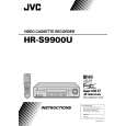
Level drop at the guide roller (supply side) C D
(3) Press the channel buttons (+, �) simultaneously to enter the manual tracking mode. This also brings tracking to the center (centre). (4) Adjust the AUDIO OUT waveform and Control pulse waveform by turning the screws (1), (2) and (3) little by little until both waveforms reach maximum. The screw (1) and (3) are for adjustment of tilt and the screw (2) for azimuth.
Head base
(2)
(1)
Level drop at the guide roller (take-up side)
Audio control head (3)
� Proper waveform variation: Always flat
AUDIO OUT � Improper waveform variation: Higher Lower CTL. P
Fig. 2-3-1c
Fig. 2-3-2a 2.3.3 Checking/Adjustment of the Audio Control Head Phase (X-Value)
Signal Mode (A1) (B) (C) (D) (E) (F) (G) (H)
Improper
Proper
(a) Guide roller
Equipment Measuring point External trigger Adjustment part
� Alignment tape(SP, stairstep, NTSC) [MHP] � PB � Oscilloscope � TP106 (PB. FM) � TP111 (D.FF) � A/C head base [Mechanism assembly] � Maximum V.PB FM waveform � A/C head positioning tool [PTU94010]
(b) Guide pole
Specified value Adjustment tool
Fig. 2-3-1d 2.3.2 Checking/Adjustment of the Height and Tilt of the Audio Control Head Note: � Set a temporary level of the height of the A/C head in advance to make the adjustment easier after the A/C head has been replaced. (See Fig.2-2-6c.)
Signal Mode Equipment Measuring point External trigger Adjustment part Specified value (A) (B) (C) (D1) (D2) (E) (F) (G)
(1) Play back the alignment tape (A1). (2) Apply the external trigger signal to D.FF (E), to observe the V.PB FM waveform at the measuring point (D). (3) Press the channel buttons (+, �) simultaneously to enter the manual tracking mode. This also brings tracking to the center (centre). (4) Loosen the screws (4) and (5), then set the A/C head positioning tool to the innermost projected part of the A/ C head. (See Fig. 2-3-3a.) (5) Turn the A/C head positioning tool fully toward the capstan. Then turn it back gradually toward the drum and stop on the second peak point position of the V.PB FM waveform output level. Then tighten the screws (4) and (5). (6) Perform the tracking operation and make sure that the V.PB FM waveform is at its maximum. If it is not at maximum, loosen the screws (4) and (5), and turn the A/C head positioning tool to bring the A/C head to a position, around where the waveform reaches its maximum for the first time. Then tighten the screws (4) and (5).
� Alignment tape(SP, stairstep, NTSC) [MHP] � PB � Oscilloscope � AUDIO OUT terminal � TP4001 (CTL. P) � TP111 (D.FF) � A/C head [Mechanism assembly] � Maximum waveform
(1) Play back the alignment tape (A). (2) Apply the external trigger signal to D.FF (E), to observe the AUDIO OUT waveform and Control pulse waveform at the measuring points (D1) and (D2) in the ALT mode.
2-17
|
|
|
> |
|