|
|
|
Kategorie
|
|
Informacje
|
|
Polecamy
|
|
|
 |
|
|
Dla tego produktu nie napisano jeszcze recenzji!
 ;
Schematy są ale można wysilić się i zrobić kolorowy skan i o większej rozdzielczości. Wtedy schematy płytek będą czytelniejsze. Całość super jako wartość merytoryczna. Wszystkie dane potrzebne do podłączenia różnego rodzajów urządzeń takich gramofon, CD itd.
 ;
Szybko, sprawnie i tanio. Serwis godny polecenia. Będę polecał innym
;
Ogólnie jest OK, z wyjątkiem obrazu płyty głównej, który jest miejscami mało czytelny, ale można sobie poradzić.
;
Dokładna dokumentacja, pomogła w szybkiej naprawie telewizora. Dziękuję!
;
jedyne do czego mogę mieć zastrzeżenie to jakość zdjęć zawartych w przesłanej instrukcji serwisowej ponieważ są fatalnej jakości, praktycznie nieczytelne. tak poza tym jestem zadowolony to jest to czego szukałem.
1.4 Service position This unit has been designed so that the Mechanism and Main board assemblies can be removed together from the chassis assembly. Before diagnosing or servicing the circuit boards, take out the major parts from the chassis assembly. 1.4.1 How to set the �Service position�
1.5
Jig RCU mode
This unit uses the following two modes for receiving remote control codes. 1) User RCU mode : Ordinary mode for use by the user. 2) Jig RCU mode : Mode for use in production and servicing.
User RCU mode Jig RCU mode
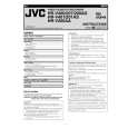
(1) Refer to the disassembly procedure and perform the disassembly of the major parts before removing the Mechanism assembly. (2) Remove the screws that fix the Mechanism assembly to the Chassis assembly. If any other screws are used to fix the boards, remove them also. (3) Remove the combined Mechanism and Main board assemblies. (4) If any other major parts are used, remove them also. (5) Connect the wires and connectors of the major parts that have been removed in steps (1) to (4). (Refer to Fig. 1-2-2d.) (6) Place the combined Mechanism, Main board and other board assemblies upside down. (7) Insert the power cord plug into the power outlet and then proceed with the diagnostics and servicing of the board assembly. Notes: � Before inserting the power cord plug into the power outlet, make sure that none of the electrical parts are able to short-circuit between the workbench and the board assembly. � For the disassembly procedure of the major parts and details of the precautions to be taken, see �1.2 Removing the major parts�. � If there are wire connections from the Main board and Mechanism assemblies to the other major parts, be sure to remove them (including wires connected to the major parts) first before performing step (2). � When carrying out diagnosis and repair of the Main board assembly in the �Service position�, be sure to ground both the Main board and Mechanism assemblies. If they are improperly grounded, there may be noise on the playback picture or FDP counter display may move even when the mechanism is kept in an inoperative status. � In order to diagnose the playback or recording of the cassette tape, set the Mechanism assembly to the required mode before placing it upside down. If the mechanism mode is changed (including ejection) while it is in an upside down position the tape inside may be damaged. � For some models, the mechanism and board assemblies are attached by connectors only. When carrying out a diagnosis or repair of the boards in the �Service position�, make sure that the connectors are not disconnected.
TP106 TP4001 PB FM CTL.P TP2253 A.PB FM TP111 D.FF Main board assembly
(not displayed)
Fig. 1-5-1a When using the Jig RCU, it is required to set the VCR to the Jig RCU mode (the mode in which codes from the Jig RCU can be received). As both of the above two modes are stored in the EEPROM, it is required to set the VCR back to the User RCU mode each time that an adjustment is made or to check that the necessary operations have been completed. These modes can be set by the operations described below. Note: � Confirm the RCU mode when exchanged parts. Since some SERVICE PARTS sets the VCR to the Jig RCU mode as initial setting. 1.5.1 Setting the Jig RCU mode (1) Unplug the power cord plug from the power outlet. (2) Press and hold the �REC� and �PAUSE� buttons on the VCR simultaneously, while plugging the power cord plug into the power outlet. Alternatively, transmit the code "7F" from the Jig RCU. (7 segment LED display model) When the VCR is set to the Jig RCU mode, the symbols ( � : � ) in the time display of the FDP are turned off. (non 7 segment LED display model) When the VCR is set to the Jig RCU mode,the "POWER" button of RCU will not work. 1.5.2 Setting the User RCU mode (1) Turn off the power. (2) Press the �REC� and �PAUSE� buttons of the VCR simultaneously. Alternatively, transmit the code �80� from the Jig RCU. 1.6 Mechanism service mode This model has a unique function to enter the mechanism into every operation mode without loading of any cassette tape. This function is called the �Mechanism service mode�. 1.6.1 How to set the �Mechanism service mode� (1) Set the VCR to the Jig RCU mode (the mode in which codes from the Jig RCU can be received). (2) Transmit the code �E5� from the Jig RCU. (3) Release the lug of the Cassette holder and then slide the Cassette holder toward the direction where the Cassette holder is loaded by manually. (4) The cassette holder lowers and, when the loading has completed, the mechanism enters the desired mode. When the VCR is set to the Mechanism service mode, the symbols (�Timer�) in the FDP (LED) are blinked. 1.6.2 How to exit from the "Mechanism service mode" (1) Unplug the power cord plug from the power outlet.
CP4002
CP3002 C3042 Micom sub clock [Timer recording model]
Fig. 1-4-1a 1-9
|
|
|
> |
|