|
|
|
Kategorie
|
|
Informacje
|
|
Polecamy
|
|
|
 |
|
|
Dla tego produktu nie napisano jeszcze recenzji!
 ;
Schematy są ale można wysilić się i zrobić kolorowy skan i o większej rozdzielczości. Wtedy schematy płytek będą czytelniejsze. Całość super jako wartość merytoryczna. Wszystkie dane potrzebne do podłączenia różnego rodzajów urządzeń takich gramofon, CD itd.
 ;
Szybko, sprawnie i tanio. Serwis godny polecenia. Będę polecał innym
;
Ogólnie jest OK, z wyjątkiem obrazu płyty głównej, który jest miejscami mało czytelny, ale można sobie poradzić.
;
Dokładna dokumentacja, pomogła w szybkiej naprawie telewizora. Dziękuję!
;
jedyne do czego mogę mieć zastrzeżenie to jakość zdjęć zawartych w przesłanej instrukcji serwisowej ponieważ są fatalnej jakości, praktycznie nieczytelne. tak poza tym jestem zadowolony to jest to czego szukałem.
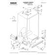
2-8. A/C HEAD UNIT
DECK POSITION : Normal
LEAD CONNECTOR a a A/C HEAD UNIT
(Removal)
1. Remove the LEAD CONNECTOR of the A/C HEAD UNIT shown in Fig. 2-8. 2. Remove the two screws (a) fastening the A/C HEAD UNIT shown in Fig. 2-8 to remove the A/C HEAD UNIT.
Head
(Installation)
1. Install the A/C HEAD UNIT shown in Fig. 2-8. Note : Never touch the head of the A/C HEAD UNIT shown in Fig. 2-8. Clean dirt on the head with alcohol, if necessary. 2. Install the LEAD CONNECTOR of the A/C HEAD UNIT shown in Fig. 2-8. 3. Perform �3-3. A/C HEAD Adjustment� and �3-4. Phase Adjustment� of �3. Interchangeability Adjustment of the Mechanism.�
Fig. 2-8
2-9. F/E HEAD
DECK POSITION : Normal
F/E HEAD
(Removal)
1. Lift the F/E HEAD shown in Fig. 2-9-1 in the direction shown by arrow A to remove it. Note : Be sure to replace the removed F/E HEAD with a new one.
A Counterclockwise
(Installation)
1. Install the F/E HEAD shown in Fig. 2-9-1. Note : Never touch the head shown in Fig. 2-9-2. Clean it with alcohol, if necessary.
Fig. 2-9-1
F/E HEAD
Head Part Never touch the Head Part.
Fig. 2-9-2
-6-
|
|
|
> |
|