|
|
|
Kategorie
|
|
Informacje
|
|
Polecamy
|
|
|
 |
|
|
Dla tego produktu nie napisano jeszcze recenzji!
 ;
jedyne do czego mogę mieć zastrzeżenie to jakość zdjęć zawartych w przesłanej instrukcji serwisowej ponieważ są fatalnej jakości, praktycznie nieczytelne. tak poza tym jestem zadowolony to jest to czego szukałem.
 ;
Wszystko w porządku.
Instrukcja czytelna i kompletna.
Dziękuję.
all right!
thank you.
;
Bardzo dobra instrukcja. Zawiera wszystko co potrzeba, polecam!
;
Instrukcja jest OK. Schematy czytelne, opisane niektóre procedury.
;
Instrukcja bardzo czytelna. zawiera co potrzeba. Polecam
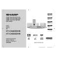
HT-CN400DVW/HT-CN400DVA/HT-CN500DVW/HT-CN500DVA
NOTES ON SCHEMATIC DIAGRAM
� Resistor: To differentiate the units of resistors, such symbol as K and M are used: the symbol K means 1000 ohm and the symbol M means 1000 kohm and the resistor without any symbol is ohm-type resistor. Besides, the one with �Fusible� is a fuse type. � Capacitor: To indicate the unit of capacitor, a symbol P is used: this symbol P means pico-farad and the unit of the capacitor without such a symbol is microfarad. As to electrolytic capacitor, the expression �capacitance/withstand voltage� is used. (CH), (TH), (RH), (UJ): Temperature compensation (ML): Mylar type (P.P.): Polypropylene type � Schematic diagram and Wiring Side of P.W.Board for this model are subject to change for improvement without prior notice. � The indicated voltage in each section is the one measured by Digital Multimeter between such a section and the chassis with no signal given. 1. In the tuner section, indicates AM indicates FM stereo 2. In the power section, a tape is being played back. � Parts marked with � 1 � ( ) are important for maintaining the safety of the set. Be sure to replace these parts with specified ones for maintaining the safety and performance of the set.
REF. NO TA301 TA302 TA303 TA304 TA305 TA306 TA307 TA308 TA309 TA310 W301
DESCRIPTION ON/STAND-BY STOP FAST FORWARD FAST REVERSE VOLUME DOWN MODE FUNCTION VOLUME UP PLAY OPEN/CLOSE MIC VOLUME [HT-CN400DVW/ HT-CN500DVW ONLY]
POSITION ON�OFF ON�OFF ON�OFF ON�OFF ON�OFF ON�OFF ON�OFF ON�OFF ON�OFF ON�OFF MAX�MIN
TYPES OF TRANSISTOR AND LED
FRONT VIEW
FRONT VIEW
FRONT VIEW
B (3) TOP VIEW E (1) C (2)
FRONT VIEW
EB C (S) (D) (G)
EC B (S) (G) (D) (1) (2) (3) 2SC2001 L
BC
E
2SK192 A PN2222 A
TIP122
DDTC114 ECA CM5783 GR 2SC1009 A 2SC1623 CM5051 2SA812
KER0002
� 32 �
|
|
|
> |
|