|
Dla tego produktu nie napisano jeszcze recenzji!
 ;
Schematy są ale można wysilić się i zrobić kolorowy skan i o większej rozdzielczości. Wtedy schematy płytek będą czytelniejsze. Całość super jako wartość merytoryczna. Wszystkie dane potrzebne do podłączenia różnego rodzajów urządzeń takich gramofon, CD itd.
 ;
Szybko, sprawnie i tanio. Serwis godny polecenia. Będę polecał innym
;
Ogólnie jest OK, z wyjątkiem obrazu płyty głównej, który jest miejscami mało czytelny, ale można sobie poradzić.
;
Dokładna dokumentacja, pomogła w szybkiej naprawie telewizora. Dziękuję!
;
jedyne do czego mogę mieć zastrzeżenie to jakość zdjęć zawartych w przesłanej instrukcji serwisowej ponieważ są fatalnej jakości, praktycznie nieczytelne. tak poza tym jestem zadowolony to jest to czego szukałem.
HT-R820THX OPERATION CHECK-4
OUTPUT LEVEL & THERMAL DETECTION
<Operation check of microprocessor by test mode>
The following is the procedure of checking detection operation of a microprocessor in false, by using test mode.
Output level detection
1. Set the unit to test mode " Test-3-3 " 1-1. Press and the hold down the CD button , then press the STANDBY/ON button when the unit is Power On.
Te st - _
1-2. Press the VIDEO 2 button, while the " Test - _ " is shown. Unit will be in the state of " Test-3-00 ".
Te st - 3- 00
1-3. Repeat and press SPEAKERS B button to the " Test-3-3 " is shown.
Te st - 3- 03
2. Apply signal (sine wave 1kHz, -1.5dBV) to MULTI CHANNEL (FL, FR, SL, SR, C) terminal, each channel. 3. Check that FM STEREO indicator is shown.
FM STEREO
FM STEREO
Test - 3-0 3
4. Press the STANDBY/ON button to power Off. (Exit from the test mode.)
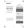
Thermal detection 1. Set the unit to test mode " Test-3-3 " Refer to the clause of " Output level detection ". 2. Connect the resistor 1.8kohms /1W between " HT2 " and " COM " terminals of P6301.
P6301 1.8 kohms 1W
TH1 TH2 COM
COM TH2 P6301
TH1
Front side
U16 NAAF-8245
POWER AMPLIFIER PC BOARD
3. Check that FM STEREO indicator is shown.
MEMORY
MEMORY
Test - 3-0 3
4. Press the STANDBY/ON button to power Off. (Exit the test mode.)
|