|
|
|
Kategorie
|
|
Informacje
|
|
Polecamy
|
|
|
 |
|
|
Dla tego produktu nie napisano jeszcze recenzji!
 ;
Dokładna dokumentacja, pomogła w szybkiej naprawie telewizora. Dziękuję!
 ;
jedyne do czego mogę mieć zastrzeżenie to jakość zdjęć zawartych w przesłanej instrukcji serwisowej ponieważ są fatalnej jakości, praktycznie nieczytelne. tak poza tym jestem zadowolony to jest to czego szukałem.
;
Wszystko w porządku.
Instrukcja czytelna i kompletna.
Dziękuję.
all right!
thank you.
;
Bardzo dobra instrukcja. Zawiera wszystko co potrzeba, polecam!
;
Instrukcja jest OK. Schematy czytelne, opisane niektóre procedury.
ICD-B7
THIS NOTE IS COMMON FOR PRINTED WIRING BOARDS AND SCHEMATIC DIAGRAMS. (In addition to this, the necessary note is printed in each block.) Common Note on Schematic Diagrams: � All capacitors are in µF unless otherwise noted. pF: µµF 50 WV or less are not indicated except for electrolytics and tantalums. All resistors are in � and 1/4 W or less unless otherwise specified. f : internal component. C : panel designation. A : B+ Line. Power voltage is dc 3V and fed with regulated dc power supply from battery terminal.
� Waveforms
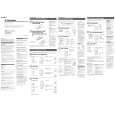
3-7. IC BLOCK DIAGRAMS
1
0.5V/div 0.1µsec/div
1.0Vp-p 4.02MHz
IC103 LM4890MMX
IC101 ta (XOUT)
� � � � �
2
1.0V/div 10µsec/div
SHUTDOWN 1 BIAS 8 VO2 7 GND 6 VDD +IN 3 -IN 4 5 VO1
2.2Vp-p 32.768kHz
BYPASS 2
IC704 1 (32KOUT)
� Voltage and waveforms are dc with respect to ground under no-signal (detuned) conditions. no mark : PB ( ) : REC � Voltages are taken with a VOM (Input impedance 10 M�). Voltage variations may be noted due to normal production tolerances. � Waveforms are taken with a oscilloscope. Voltage variations may be noted due to normal production tolerances. � Circled numbers refer to waveforms. � Signal path. E : PB a : REC
3
0.5V/div 10µsec/div
1.2Vp-p 32.768kHz
IC704 8 (OSCOUT)
4
1.0V/div 0.2µsec/div 3.2Vp-p 5MHz
IC704 RS5C348A-E2
IC703
ul (X2)
Common Note on Printed Wiring Boards: � X : parts extracted from the component side. � Y : parts extracted from the conductor side. � �
f
32KOUT
1
32 kHz OUTPUT CONTROL
: internal component. : Pattern from the side which enables seeing.
COMPARATOR W COMPARATOR
ALARM W REGISTER (WEEK, MIN, HOUR) ALARM D REGISTER (MIN, HOUR)
VDD
Caution: Pattern face side: (SIDE B) Parts face side: (SIDE A) � Lead Layouts
D
10 VDD
Parts on the pattern face side seen from the pattern face are indicated. Parts on the parts face side seen from the parts face are indicated.
SCLK 2 ADDRESS REGISTER SO 3 I/O CONTROL SI 4 SHIFT REGISTER
TIMER COUNTER SEC, MIN, HOUR, WEEK, DAY, MONTH, YEAR
DIV
DIVIDER CORRECTION
9 OSC 8
OSCIN OSCOUT
ADDRESS DECODER
INTERRUPT CONTROL OSC DETECT
Lead layout of conventional IC
VSS 5 VOLTAGE DETECT
7 6
CE INTR
14
14
|
|
|
> |
|