|
Dla tego produktu nie napisano jeszcze recenzji!
APPLICATIONS
For your convenience, we�ve included several application diagrams to help you plan your own system installation. Figures 1 through 3 show how to configure the Kappa 52a for stereo, bridged-mono, and tri-mode operation.
Figure 1. This wiring diagram shows a Kappa 52a amplifier set to stereo to drive a pair of full-range speakers.
For system expansion ideas, see the next page.
NOTE: For simplicity, Figures 1 through 3 do not show power, remote, and input connections.
Set Mode Switch To STEREO
(on top panel)
REM
�R+
+
L
�
Set Filter Switches To FLAT
(on top panel)
KAPPA 52a
(rear panel)
+ +
R Speaker
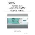
Figure 2. This wiring diagram shows a Kappa 52a amplifier set to bridge (mono) to drive a single subwoofer.
L Speaker
Set Mode Switch To BRIDGE (on top panel)
REM
�R+
+
L
�
Set Filter Switches
(on top panel)
KAPPA 52a
(rear panel)
+
Subwoofer
-
Figure 3. This wiring diagram shows a Kappa 52a amplifier set for tri-mode operation. For a desired crossover frequency, use the chart to select a lowpass inductor for the subwoofer, and corresponding high-pass capacitors for left and right speakers.
FREQUENCY
Crossover 75Hz 100 Hz 125 Hz 150 Hz 175 Hz 200 Hz
Set Mode Switch To STEREO
(on top panel)
REM
�R+
+
L
�
Set Filter Switches To FLAT
(on top panel)
KAPPA 52a
(rear panel)
R Speaker
+
Capacitor Inductor
L Speaker
Capacitor
INDUCTOR
6 dB/oct. LP (4 ohm) 8.0 mH 6.4 mH 5.0 mH 4.2 mH 3.6 mH 3.2 mH
CAPACITOR
6 dB/oct. HP (4 ohm) 530 µF 400 µF 318 µF 265 µF 227 µF 198 µF
+
Owner�s Manual/Installation Guide � 3
-
+
Subwoofer
|