|
Dla tego produktu nie napisano jeszcze recenzji!
 ;
Dokładna dokumentacja, pomogła w szybkiej naprawie telewizora. Dziękuję!
 ;
jedyne do czego mogę mieć zastrzeżenie to jakość zdjęć zawartych w przesłanej instrukcji serwisowej ponieważ są fatalnej jakości, praktycznie nieczytelne. tak poza tym jestem zadowolony to jest to czego szukałem.
;
Wszystko w porządku.
Instrukcja czytelna i kompletna.
Dziękuję.
all right!
thank you.
;
Bardzo dobra instrukcja. Zawiera wszystko co potrzeba, polecam!
;
Instrukcja jest OK. Schematy czytelne, opisane niektóre procedury.
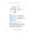
KD-SH909R Removing the trigger arm (See Fig.18 and 19)
Prior to performing the following procedure, remove the top cover, the connector board and the clamper unit. 1. Turn the trigger arm in the direction of the arrow to release the joint k and pull out upward.
Joint k
Trigger arm
CAUTION: When reassembling, insert the part l and m of the trigger arm into the part n and o at the slot of the chassis rivet assembly respectively and join the joint k at a time.
Chassis rivet assembly
Fig.18
Part n Trigger arm Part l Part m Part o
Chassis rivet assembly
Fig.19
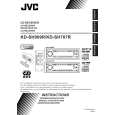
Removing the top plate assembly (See Fig.20)
Prior to performing the following procedure, remove the top cover, the connector board, the chassis unit, and the clamper assembly. 1. Remove the screw H. 2. Move the top plate assembly in the direction of the arrow to release the two joints p.
Top plate assembly
H
Joints p
q
3. Unsolder the wire marked q if necessary.
Fig.20
1-16
|