|
|
|
Kategorie
|
|
Informacje
|
|
Polecamy
|
|
|
 |
|
|
Dla tego produktu nie napisano jeszcze recenzji!
 ;
Schematy są ale można wysilić się i zrobić kolorowy skan i o większej rozdzielczości. Wtedy schematy płytek będą czytelniejsze. Całość super jako wartość merytoryczna. Wszystkie dane potrzebne do podłączenia różnego rodzajów urządzeń takich gramofon, CD itd.
 ;
Szybko, sprawnie i tanio. Serwis godny polecenia. Będę polecał innym
;
Ogólnie jest OK, z wyjątkiem obrazu płyty głównej, który jest miejscami mało czytelny, ale można sobie poradzić.
;
Dokładna dokumentacja, pomogła w szybkiej naprawie telewizora. Dziękuję!
;
jedyne do czego mogę mieć zastrzeżenie to jakość zdjęć zawartych w przesłanej instrukcji serwisowej ponieważ są fatalnej jakości, praktycznie nieczytelne. tak poza tym jestem zadowolony to jest to czego szukałem.
D
C
E
B
A
F
40
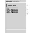
6. Multi-CD player 8. Note: (sold separately) Depending on kind of vehicle, the function 18. Connecting cords with RCA pin plugs sure connect 2* 5* and 4* to 3*. (sold separately) 1. This Product 4. IP-BUS cable 2. Rear output 5* 4* 20. Blue/white 12 V DC). 21. System remote control When not using this terminal, To Auto-antenna relay control terminal (max. 300 mA 12 V DC). 10. Cap (1*) 5. IP-BUS input (Blue) 7. Fuse 3. Antenna jack (sold separately)
1
type of vehicle, never connect 6* and 7*. 25. Left 26. Right ON/OFF. 27. Rear Speaker 28. Perform these connections when using 17. Speaker leads White : Front left + White/black : Front left â� the optional amplifier. Gray : Front right + Gray/black : Front right â� + â� + â�
1
of 3* and 5* may different. In this case, be
1*
3* 2* 19. Power amp
9. Connect leads of the same To system control terminal of
color to each other . the power amp (max. 300 mA
2
2
do not remove the cap. 22. Blue/white (7*)
11. (3*) 12. Yellow (2*) 23. Blue/white (6*)
KEH-P2033R/XM/EW
Back-up To terminal always supplied 24. The pin position of the ISO connector will differ (or accessory) with power regardless of depends on the type of vehicle. Connect 6* and 7*
ignition switch position. when Pin 5 is an antenna control type. In another
13. (5*) 14. Red (4*)
Accessory To electric terminal controlled (or back-up) by ignition switch (12 V DC)
3
3
15. Black (ground)
To vehicle (metal) body.
4
4
16. ISO connector Green : Rear left
Note: Green/black : Rear left In some vehicles, the ISO connector may be Violet : Rear right divided into two. In this case, be sure to Violet/black : Rear right connect to both connectors.
|
|
|
> |
|