|
|
|
Kategorie
|
|
Informacje
|
|
Polecamy
|
|
|
 |
|
|
Dla tego produktu nie napisano jeszcze recenzji!
 ;
...instruction is ok.
...instrukcja jest ok.
Thanks/Dzięki
;
Documentation made available quickly and It is good quality. Thanks.
KF-50SX100/50SX100K/50SX100U
RM-903 RM-903 RM-903
3-4. RGB OUTPUT LEVEL ADJUSTMENT
1. Input the colour bar signal (100% white) to AV4 and select AV4. 2. Setting MCP 26 MCP 33 MCP 34 Gamma DPIC-Level DC-Tran 0 0 0
3. R adjustment 1) Set �D9512 TPN 8 T-PATN RGB� to 1. 2) Adjust by changing data of �LCD-DR 3 R EVEN VR� to the vertical stripe (brightness difference every two dots) to minimum. 3) Write the data into memory. 4. G adjustment 1) Set �D9512 TPN 8 T-PATN RGB� to 2. 2) Adjust by changing data of �LCD-DR 8 G EVEN VR� to the vertical stripe (brightness difference every two dots) to minimum. 3) Write the data into memory. 3. B adjustment 1) Set �D9512 TPN 8 T-PATN RGB� to 4. 2) Adjust by changing data of �LCD-DR 3 B EVEN VR� to the vertical stripe (brightness difference every two dots) to minimum. 3) Write the data into memory.
3. Connect an oscilloscope to pin 5 (R), pin 3 (G) or pin 1 (B) of CN702 on BB board. 4. Initialising b Feature setting 6 Pict Boost Bypass ON 5. Adjust drive; A and cutoff; B by changing data of followings as shown in the figure. MCP 7 MCP 9 MCP 10 MCP 11 R-Drive G-Drive B-Drive R-Cutoff
MCP 12 G-Cutoff MCP 13 B-Cutoff 6. Write the data into memory. CN702:5 (R) A : 1.4 ± 0.025Vp-p B : 2.275 ± 0.025Vp-p CN702:3 (G) A : 1.4 ± 0.025Vp-p B : 2.275 ± 0.025Vp-p CN702:1 (B) A : 1.4 ± 0.025Vp-p B : 2.275 ± 0.025Vp-p
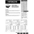
Screen magnify Should be minimize bright difference every two dots.
Fig. 3-3
3-6. SUB BRIGHT ADJUSTMENT
1. Receive the monoscope signal. 2. Mode PICTURE Personal
Fig. 3-2
SCREEN SIZE Full 3. Adjust by changing data of �D9512 IM 3 SUB BRT� so that the border between 0 IRE and 10 IRE becomes distinct. 4. Write the data into memory.
3-5. VERTICAL STRIPE ADJUSTMENT
1. Setting D9512 TES 2 G-LUT SW 0 D9512 TPN 0 T-PATN SW 1 D9512 TPN 1 T-SIG SEL 0 D9512 TPN 2 PATN DIR 1 D9512 TPN 3 SIG LV DIR 0 D9512 TPN 5 B-LV 15 D9512 TPN 6 G-LV 15 D9512 TPN 7 R-LV 15 2. Check the middle luminance of mono flat field on the screen.
3-7. SCREEN CENTER ADJUSTMENT
3-7-1. Horlzontal center adjustment 50Hz : PAL SPCB 60Hz : PAP (PAL SPCB for main and sub) 1) Adjust H center by changing data of "IP00C741A 1.OACTHST-L". 3-7-2. Vertical center adjustment 50Hz : PAL SPCB 60Hz : INDEX (1) 50Hz adjustment Input PAL SPCB and adjust V center by changing data of "IP00C741A 3. SYRDLY".
� 43 �
|
|
|
> |
|