|
|
|
Kategorie
|
|
Informacje
|
|
Polecamy
|
|
|
 |
|
|
Dla tego produktu nie napisano jeszcze recenzji!
 ;
Dokładna dokumentacja, pomogła w szybkiej naprawie telewizora. Dziękuję!
 ;
jedyne do czego mogę mieć zastrzeżenie to jakość zdjęć zawartych w przesłanej instrukcji serwisowej ponieważ są fatalnej jakości, praktycznie nieczytelne. tak poza tym jestem zadowolony to jest to czego szukałem.
;
Wszystko w porządku.
Instrukcja czytelna i kompletna.
Dziękuję.
all right!
thank you.
;
Bardzo dobra instrukcja. Zawiera wszystko co potrzeba, polecam!
;
Instrukcja jest OK. Schematy czytelne, opisane niektóre procedury.
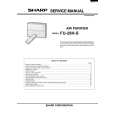
KS-FX473R/KS-FX470R
Pinch-roller (R) assembly S support plate C washer A arm spring (b) Shaft Pinch-roller (F) assembly
D
A arm spring (a) Shaft
FF roller
Playback head
Remove the P arm spring (r) from the chassis.
Remove the P arm spring (f) from the chassis.
P arm spring (r)
P arm spring (f)
Fig.2
Removing the playback head (See Fig.2)
Prior to performing the following procedure, remove the direction switch board and the FF / REW lever assembly. 1. Remove the screw D attaching the playback head. 2. Remove the C washer and pull out the FF roller. 3. Remove the S support plate, the A arm spring (a) and (b), the playback head. ATTENTION: The A arm spring (a) differs from the A arm spring (b).
Removing the pinch-roller (R) and (F) assembly (See Fig.2)
Prior to performing the following procedure, remove the direction switch board and the FF / REW lever assembly. 1. Remove the P arm spring (f) in the pinch-roller (F) assembly from the chassis. 2. Remove the P arm spring (r) in the pinch-roller (R) assembly from the chassis. 3. Draw out the pinch roller (F) and (R) assembly from the shaft. ATTENTION: The P arm spring (f) differs from the P arm spring (r). ATTENTION: The pinch roller (F) assembly differs from the pinch roller (R) assembly.
1-9
|
|
|
> |
|