|
|
|
Kategorie
|
|
Informacje
|
|
Polecamy
|
|
|
 |
|
|
Dla tego produktu nie napisano jeszcze recenzji!
 ;
...instruction is ok.
...instrukcja jest ok.
Thanks/Dzięki
;
Documentation made available quickly and It is good quality. Thanks.
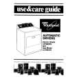
2-6. PICTURE TUBE REMOVAL
Two DGC holders 7
Degaussing coils 8 2 Chassis assy Spring Extension 9
C Board 3 4 VM Board
Neck assy 5 Deflection yoke 6
Anode cap 1
10 Four PT screws (M)
11 Picture tube
Cushion
�
REMOVAL OF ANODE-CAP
Note : Short circuit the anode of the picture tube and the anode cap to the metal chassis, CRT shield or carbon paint on the CRT, after removing the anode.
* REMOVING PROCEDURES.
c
a
b b
Anode button
1 Turn up one side of the rubber cap in the direction indicated by the arrow a
2 Using a thumb pull up the rubber cap 3 When one side of the rubber cap is firmly in the direction indicated by the separated from the anode button, the arrow b anode-cap can be removed by turning up the rubber cap and pulling it up in the direction of the arrow c
�
1 2 3
HOW TO HANDLE THE ANODE-CAP
To prevent damaging the surface of the anode-cap do not use sharp materials. Do not apply too great a pressure on the rubber, as this may cause damage to the anode connector. A metal fitting called a shatter hook terminal is fitted inside the rubber cap. Do not turn the rubber foot over excessively this may cause damage if the shatter hook sticks out.
14
|
|
|
> |
|