|
Dla tego produktu nie napisano jeszcze recenzji!
 ;
Instrukcja jest OK. Schematy czytelne, opisane niektóre procedury.
 ;
Instrukcja bardzo czytelna. zawiera co potrzeba. Polecam
;
...instrukcja serwisowa w pełni czytelna i kompletna. Dziękuję!
;
Instrukcja Serwisowa jest kompletna i czytelna. Dziękuję!
;
Wszystko OK!
Dokumentacja jest czytelna.
Dziękuję.
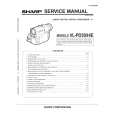
2-9. PICTURE TUBE REMOVAL
7 DGC holder
Degaussing coils 8
Spring tension 9 C board 3 VM board 4 2 Chassis assy
Neck assy 5
Deflection yolk 6
Anode cap 1 10 Four PT screws
Picture tube 11
Cushion
�
REMOVAL OF ANODE-CAP
* REMOVING PROCEDURES.
c
Note : Short circuit the anode of the picture tube and the anode cap to the metal chassis, CRT shield or carbon paint on the CRT, after removing the anode.
a
b b
Anode button
1 Turn up one side of the rubber cap in the direction indicated by the arrow a
�
1 2 3
HOW TO HANDLE THE ANODE-CAP
2 Using a thumb pull up the rubber cap 3 When one side of the rubber cap is firmly in the direction indicated by the separated from the anode button, the arrow b anode-cap can be removed by turning up the rubber cap and pulling it up in the direction of the arrow c
To prevent damaging the surface of the anode-cap do not use sharp materials. Do not apply too great a pressure on the rubber, as this may cause damage to the anode connector. A metal fitting called a shatter hook terminal is fitted inside the rubber cap. Do not turn the rubber foot over excessively this may cause damage if the shatter hook sticks out.
23
 $4.99 KV-28DS60U SONY
Schematy Zestaw schematów dla tego urządzenia. Plik PDF zawierający schematy będzie dostarczony na Twó…
|