|
|
|
Kategorie
|
|
Informacje
|
|
Polecamy
|
|
|
 |
|
|
Dla tego produktu nie napisano jeszcze recenzji!
 ;
Dokładna dokumentacja, pomogła w szybkiej naprawie telewizora. Dziękuję!
 ;
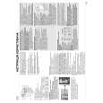
jedyne do czego mogę mieć zastrzeżenie to jakość zdjęć zawartych w przesłanej instrukcji serwisowej ponieważ są fatalnej jakości, praktycznie nieczytelne. tak poza tym jestem zadowolony to jest to czego szukałem.
;
Wszystko w porządku.
Instrukcja czytelna i kompletna.
Dziękuję.
all right!
thank you.
;
Bardzo dobra instrukcja. Zawiera wszystko co potrzeba, polecam!
;
Instrukcja jest OK. Schematy czytelne, opisane niektóre procedury.
SECTION 3 SET-UP ADJUSTMENTS
� � �
When complete readjustment is necessary or a new picture tube is installed, carry out the following adjustments. Unless there are specific instructions to the contrary, carry out these adjustments with the rated power supply. Unless there are specific instructions to the contrary, set the controls and switches to the following settings : Contrast .................................. normal
Carry out the adjustments in the following order : 3-1. Beam Landing. 3-2. Convergence. 3-3. Focus. 3-4. White Balance. Note : Test equipment required. 1. Color bar/pattern generator. 2. Degausser. 3. Oscilloscope. 4. Digital multimeter.
Brightness .................................. normal
3-1. Beam Landing
Caution : Preparation : 1. 2. In order to reduce the influence of geomagnetism on the set�s picture tube, face it in an easterly or westerly direction. Switch on the TV set�s power and degauss with a degausser. High voltages are present on the Deflection yoke terminals - take care when handling the Deflection yoke whilst carrying out adjustments. (2) Landing Note : Before carrying out the following adjustments adjust the magnets as indicated below [See Fig.3-4]. 1. Input a crosshatch signal from the signal generator. 2. Rough-adjust the focus and horizontal convergence. 3. Switch from the crosshatch pattern to an all-red pattern. 4. Move the deflection yoke backwards and adjust with the purity magnet so that the red is at the centre and it aligns symmetrically [See Fig.3-5]. 5. Move the deflection yoke forward to the point where the entire screen just becomes red [Mark its position]. 6. Move the deflection yoke further forward until the screen just changes colour at the edges. [Mark its position] 7. Position the deflection yoke between the two marks indicated above. 8. Input a crosshatch pattern from the pattern generator and rotate the deflection yoke so that the horizontal lines are parallel with the top and bottom of the screen. 9. When the position of the deflection yoke has been determined, fasten it with its fixing screw. 10. Switch the pattern generator to green then blue and confirm the purity. 11. If the beam does not land correctly in all the corners of the screen, use disk magnets to correct it. [Confirm the corner landing for green and blue]
Fig.3-3
G2 G1
(1) Adjustment of Correction Magnet for Y-Splitting Axis. 1. 2. 3. 4. 5. 6. Input a crosshatch signal from the pattern generator. Set the Picture control to minimum and confirm that the Brightness control is set to normal. Position the neck assembly as indicated in Fig.3-3. Loosen the deflection yoke fixing screw. Move the deflection yoke as far forward as is possible. Adjust the upper and lower pin symmetrically by opening or closing the Y-splitting axis correction magnets located on the neck assembly. [See Fig 3-1 and Fig 3-2] Return the deflection yoke to its original position and re-tighten its fixing screw.
7.
Fig.3-1 Y-splitting axis correction magnet
Neck assy
+
G3
Align the edge of the neck assy with the edge of the G2 grid on the G3 side.
Fig.3-2
20
|
|
|
> |
|