|
Dla tego produktu nie napisano jeszcze recenzji!
 ;
jedyne do czego mogę mieć zastrzeżenie to jakość zdjęć zawartych w przesłanej instrukcji serwisowej ponieważ są fatalnej jakości, praktycznie nieczytelne. tak poza tym jestem zadowolony to jest to czego szukałem.
 ;
Wszystko w porządku.
Instrukcja czytelna i kompletna.
Dziękuję.
all right!
thank you.
;
Bardzo dobra instrukcja. Zawiera wszystko co potrzeba, polecam!
;
Instrukcja jest OK. Schematy czytelne, opisane niektóre procedury.
;
Instrukcja bardzo czytelna. zawiera co potrzeba. Polecam
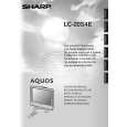
LC-20S4E
8. Remove the 2 lock screws from the main PWB and undo the hooks a. Detach the chassis frame, together with its terminals, from the main PWB. 9. Remove the 2 lock screws from the sub PWB and undo the hooks b, c, d and e. Detach the chassis frame together with its terminals, from the sub PWB. 10. Remove the 3 lock screws from the operation PWB, and detach the operation PWB. 11. Remove the 3 lock screws from the inverter PWB and take out the inverter PWB. 12. Remove the 2 lock screws from the R/C, LED PWB and take out the R/C, LED PWB. 13. Remove the 2 lock screws each from the right and left speakers and take out both the speakers.
9
8 Operation PWB 10
Main PWB b Chassis Frame a
c
Sub PWB
11
d
e
Inverter PWB
Speaker (R)
Speaker (L)
13
R/C,LED PWB
12
13
9
|