|
Dla tego produktu nie napisano jeszcze recenzji!
 ;
Dokładna dokumentacja, pomogła w szybkiej naprawie telewizora. Dziękuję!
 ;
jedyne do czego mogę mieć zastrzeżenie to jakość zdjęć zawartych w przesłanej instrukcji serwisowej ponieważ są fatalnej jakości, praktycznie nieczytelne. tak poza tym jestem zadowolony to jest to czego szukałem.
;
Wszystko w porządku.
Instrukcja czytelna i kompletna.
Dziękuję.
all right!
thank you.
;
Bardzo dobra instrukcja. Zawiera wszystko co potrzeba, polecam!
;
Instrukcja jest OK. Schematy czytelne, opisane niektóre procedury.
LC-26GA5U LC-32GA5U
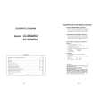
11. Remove the two lock screws from the LCD control PWB, and detach the LCD control PWB and heat sink. 12. Remove the six lock screws from the power PWB, and detach the power PWB. 13. Remove the four lock screws from the chassis frame (S), and detach the chassis frame (S). 14. Remove the AV PWB. 14-1. Remove the six lock screws from the AV unit, and detach the AV unit. 14-2. Remove the four lock screws from the chassis frame (L), and detach the chassis frame (L) 15. Remove the four lock screws from the inverter PWB, and detach the inverter PWB. (only for LC-26GA5U) 15. Remove the four lock screws from the inverter-1 PWB, and detach the inverter-1 PWB. (only for LC-32GA5U) 16. Remove the four lock screws from the inverter-2 PWB, and detach the inverter-2 PWB. (only for LC-32GA5U) 17. Remove the hree lock screws from the inverter-GND PWB, and detach the inverter-GND PWB. (only for LC-26GA5U) 17. Remove the six lock screws from the inverter-GND PWB, and detach the inverter-GND PWB. (only for LC-32GA5U) 18. Remove the four lock screws from the reinforcement angle (bottom), and detach the reinforcement angle (bottom). (only for LC-26GA5U) 19. Remove the two lock screws from the LCD panel unit, and detach the LCD panel unit. (only for LC-26GA5U) 19. Remove the one lock screw from the LCD panel unit, and detach the LCD panel unit. (only for LC-32GA5U)
11 LCD CONTROL PWB
LC-26GA5U LC-32GA5U
17 17
LC-32GA5U LC-26GA5U
15 15
LC-32GA5U
19 Heat Sink
LC-26GA5U
19
16
Chassis Frame (L) 14-2
Chassis Frame (S)
POWER PWB
12 18 13 14-1 AV PWB 14-1 13 18
LC-26GA5U
Reinforcement Angle (Bottom)
17
 $4.99 LC-26GA5U SHARP
Schematy Zestaw schematów dla tego urządzenia. Plik PDF zawierający schematy będzie dostarczony na Twó…
|