|
Dla tego produktu nie napisano jeszcze recenzji!
 ;
Wszystko w porządku.
Instrukcja czytelna i kompletna.
Dziękuję.
all right!
thank you.
;
Bardzo dobra instrukcja. Zawiera wszystko co potrzeba, polecam!
 ;
Instrukcja jest OK. Schematy czytelne, opisane niektóre procedury.
;
Instrukcja bardzo czytelna. zawiera co potrzeba. Polecam
;
...instrukcja serwisowa w pełni czytelna i kompletna. Dziękuję!
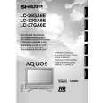
LC-26GA6E/LC-26BV6E LC-26GA5E LC-32GA6E/LC-32BV6E LC-32GA5E LC-37GA6E
7. Disconnect all the connectors from all the PWBs. 8. Remove the MAIN, HDMI and COMPONENT PWBs. 8-1. Remove the 3 lock screws 9 and the 2 lock screws 0. Detach the Chassis Frame. 8-2. Remove the 8 lock screws q and detach the MAIN PWB and HDMI/COMPONENT unit. 8-3. Remove the 4 lock screws w and detach the COMPONENT PWB from HDMI PWB. 9. Remove the 2 lock screws e and detach the R/C,LED PWB 10. Remove the 3 (LC-26GA6E) / 6 (LC-32GA6E) lock screws r and detach the INVERTER GND PWB. 11. LC-26GA6E : Remove the 4 lock screws t and detach the INVERTER PWB. LC-32GA6E : Remove the 8 lock screws t and detach the INVERTER-A and INVERTER-B PWBs. 12. Remove the 6 lock screws y and detach the LCD CONTROLLER PWB and Heat Sink. 13. Remove the 6 lock screws u and detach the POWER PWB. 14. Remove the 2 lock screws i and detach theSP BOX (L) and (R). (LC-26GA6E only)
CN7601 P2207 SC4651 SC4652 SC4601
SC2001 P2205 P2206 P7704
P2006
P7707
P7705
CN704 CN706
P2201 P1001 P1006 CN707
P1401
P1003 P1301
P1901 P2103 P2102
P1902 P2101
P4001
8
|