|
|
|
Kategorie
|
|
Informacje
|
|
Polecamy
|
|
|
 |
|
|
Dla tego produktu nie napisano jeszcze recenzji!
 ;
Dokładna dokumentacja, pomogła w szybkiej naprawie telewizora. Dziękuję!
 ;
jedyne do czego mogę mieć zastrzeżenie to jakość zdjęć zawartych w przesłanej instrukcji serwisowej ponieważ są fatalnej jakości, praktycznie nieczytelne. tak poza tym jestem zadowolony to jest to czego szukałem.
;
Wszystko w porządku.
Instrukcja czytelna i kompletna.
Dziękuję.
all right!
thank you.
;
Bardzo dobra instrukcja. Zawiera wszystko co potrzeba, polecam!
;
Instrukcja jest OK. Schematy czytelne, opisane niektóre procedury.
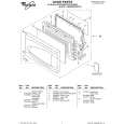
SECTION 3 DISASSEMBLY
3.1 DISASSEMBLY PROCEDURE CAUTION AT DISASSEMBLY: � Make sure that the power cord is disconnected from the outlet. � Pay special attention not to break or damage the parts. � When removing each board, remove the connectors as required. Taking notes of the connecting points (connector numbers) makes service procedure manageable. � Make sure that there is no bent or stain on the connectors before inserting, and firmly insert the connectors. 3.1.1 REMOVING THE STAND (1) Remove the JACK COVER. (2) Remove the 2 screws [A], then remove the STAND COVER. (3) Remove the 2 screws [W], then remove the CABLE COVER. (4) Remove the 4 screws [B], then remove the STAND. 3.1.2 REMOVING THE REAR COVER � Remove the STAND. (1) Remove the 8 screws [C], 1 screw [D] and 2 screws [E], then remove the REAR COVER. 3.1.3 REMOVING THE POWER PWB � Remove the STAND. � Remove the REAR COVER. (1) Remove the 4 screws [G] and 1 screw [H], then remove the TERMINAL BASE. (2) Remove the 8 screws [F], then remove the BACK BRACKET. (3) Remove the 6 screws [J], then remove the POWER PWB SHIELD. (4) Remove the 5 screws [K], then remove the POWER PWB. 3.1.4 REMOVING THE MAIN PWB � Remove the STAND. � Remove the REAR COVER. � Remove the TERMINAL BASE. � Remove the BACK BRACKET. � Remove the POWER PWB SHIELD. (1) Remove the 7 screws [L] and 2 screws [N], then remove the MAIN PWB SHIELD. (2) Remove the 6 screws [M], then remove the MAIN PWB. 3.1.5 REMOVING THE KEY PWB � Remove the STAND. � Remove the REAR COVER. (1) Remove the 2 screws [P], then remove the KEY PWB. 3.1.6 REMOVING THE LED PWB � Remove the STAND. � Remove the REAR COVER. (1) Remove the 2 screws [Q], then remove the LED PWB. 3.1.7 REMOVING THE SPEAKER � Remove the STAND. � Remove the REAR COVER. (1) Remove the 6 screws [R], then remove the SPEAKER (L/ R). CAUTION: Please do not disassembly the SPEAKER. When the speaker is decomposed, the performance cannot be kept. 3.1.8 REMOVING THE LCD PANEL UNIT � Remove the STAND. � Remove the REAR COVER. � Remove the TERMINAL BASE. � Remove the BACK BRACKET. (1) Remove the 6 screws [S], then remove the MAIN BASE. (2) Remove the 6 screws [T], then remove the FRONT PANEL. (3) Remove the 2 screws [U], then remove the TOP FRAME. (4) Remove the 2 screws [V], then remove the BOTTOM FRAME. NOTE: � Pay special attention not to break or damage on the FRONT PANEL. � The LCD PANEL UNIT is fixed to the FRONT PAMEL (at the back side)by using double-side adhesive tapes. To remove the LCD PANEL UNIT, remove the adhesive tape on the FRONT PANEL slowly.
1-10 (No.YA314)
|
|
|
> |
|