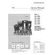
|
|
|
Kategorie
|
|
Informacje
|
|
Polecamy
|
|
|
 |
|
|
Dla tego produktu nie napisano jeszcze recenzji!
 ;
Dokładna dokumentacja, pomogła w szybkiej naprawie telewizora. Dziękuję!
 ;
jedyne do czego mogę mieć zastrzeżenie to jakość zdjęć zawartych w przesłanej instrukcji serwisowej ponieważ są fatalnej jakości, praktycznie nieczytelne. tak poza tym jestem zadowolony to jest to czego szukałem.
;
Wszystko w porządku.
Instrukcja czytelna i kompletna.
Dziękuję.
all right!
thank you.
;
Bardzo dobra instrukcja. Zawiera wszystko co potrzeba, polecam!
;
Instrukcja jest OK. Schematy czytelne, opisane niektóre procedury.
Alignment and Adjustments
2. Cassette Deck
2-1. To Adjust Tape Speed
Notes 1) Measuring tape: i) MTT-111 (or equivalent) (Tapes recorded with 3kHz) ii) MTT-5512 (or equivalent) 2) Connect the SPK OUT of the MAIN PCB to the frequency counter as in figure 1-5.
MAIN PCB SPK OUT output Figure 1-5 Frequency Counter
2-2. To Adjust PlayBack Level/REC
Notes 1) Before the actual adjustment, clean the play/recording head. 2) Measuring tape : i) MTT-114N(or equivalent 10kHz AZIMUTH control) ii) MTT-5512 3) The cassette deck is connections as shown in figure 1-7.
Step
Item
Pre-Setup Condition
Pre-Setup 1) Deck 1:MTT-111 2) Press PLAY SW button 3) Deck 2:Same as above
To Adjust
Standard
Remark
1. Adjust Deck 1 Play Level
Turn VSR1 to left and right (FRONT PCB) 3KHz ±1% range Step Item Pre-Setup Condition Pre-Setup After putting MTT AZIMUTH SPK OUT (VTVM is connected to the scope)
MAIN PCB
SPK OUT
VTVM
1
NOR SPEED Control
SPK OUT (connected to the frequency counter)
To Adjust
Standard
Remark
114N into Deck 1 - Press FWD PLAY button.
1
Recording /Play head Oscilloscope
- T the control urn screw to as shown in Figure 1-6.
Max output and same phase (both channels)
After adjustment secure it with REGION LOCK.
(GND)
In Out Figure 1-7
2. Adjust Deck 2 Play Level/ REC BIAS
Step Item Pre-Setup Condition
SPK OUT
AZIMUTH control screw
(RVS Play)
AZIMUTH control screw
(FWD Play)
Pre-Setup After putting MTT 114N into Deck 2 - Press FWD PLAY button.
To Adjust
Standard
Remark
Figure 1-6
1 AZIMUTH
(VTVM is connected to the scope)
- T the control urn screw to as shown in Figure 1-6.
MAX OUTPUT and same phase (both channels)
After adjustment secure it with REGION LOCK.
Audio OSC.
SET (MAIN PCB)
VTVM
Oscilloscope
After putting MTT -
2
IN AUX IN TP SPK OUT
Recording Bias Voltage
5512 into Deck 2 Fig 1-8
1) Press REC PLAY button. 2) T APE PCB JCW3 ,connected
- T JSR2L,JSR2R urn to the right and left
CHECK TO 7mV(±0.5mV)
IN OUT
to VTVM
Figure 1-8
Samsung Electronics
1-3
|
|
|
> |
|