|
Dla tego produktu nie napisano jeszcze recenzji!
 ;
Schematy są ale można wysilić się i zrobić kolorowy skan i o większej rozdzielczości. Wtedy schematy płytek będą czytelniejsze. Całość super jako wartość merytoryczna. Wszystkie dane potrzebne do podłączenia różnego rodzajów urządzeń takich gramofon, CD itd.
 ;
Szybko, sprawnie i tanio. Serwis godny polecenia. Będę polecał innym
;
Ogólnie jest OK, z wyjątkiem obrazu płyty głównej, który jest miejscami mało czytelny, ale można sobie poradzić.
;
Dokładna dokumentacja, pomogła w szybkiej naprawie telewizora. Dziękuję!
;
jedyne do czego mogę mieć zastrzeżenie to jakość zdjęć zawartych w przesłanej instrukcji serwisowej ponieważ są fatalnej jakości, praktycznie nieczytelne. tak poza tym jestem zadowolony to jest to czego szukałem.
MJ-D707, MJ-17D
7.2 DIAGNOSIS
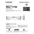
7.2.1 DISASSEMBLY Removal of the Servo Mechanism Assy
1 Remove the screw A. 2 Disconnect the connectors (CN102, CN103, CN105), open the hook of part A, and tilt the upper side of the CORE MAIN UNIT ASSY to the front. CN105 3 Disconnect the connector (CN101) at the rear of the CORE MAIN UNIT ASSY and remove the CORE MAIN UNIT ASSY. 4 After the Carrier has been pushed in, move the Upper Slider to Screw A the rear and stop it at the position where the Under Slider starts to move.
2
CN103
1
2
CN101
Part A
CN102
4
Rear Side
Upper Slider
2
3
CORE MAIN UNIT ASSY
Carrier
Move
5 Shift part B to the position shown in the figure while raising the Under Slider. (At the same time, the Upper Slider moves to the front.) 6 Remove the Lock Plate. (One screw B)
Under Slider
Under Slider Upper Slider
5
Part B
7 Remove the Servo Mechanism Assy.
Screw B
6
Lock Plate
Servo Mechanism Assy
Caution for the time of installation of the servo mechanism assy
Move the MD Pick-up to the innermost circumference. After installation of the servo mechanism assembly, shift the Upper Slider to the rear. (The Under Slider moves at the same time, and the servo mechanism assy is fixed. When the Under Slider is slide, this becomes the reason for switching ring catching.)
7
61
|