|
|
|
Kategorie
|
|
Informacje
|
|
Polecamy
|
|
|
 |
|
|
Dla tego produktu nie napisano jeszcze recenzji!
 ;
Wszystko w porządku.
Instrukcja czytelna i kompletna.
Dziękuję.
all right!
thank you.
;
Bardzo dobra instrukcja. Zawiera wszystko co potrzeba, polecam!
 ;
Instrukcja jest OK. Schematy czytelne, opisane niektóre procedury.
;
Instrukcja bardzo czytelna. zawiera co potrzeba. Polecam
;
...instrukcja serwisowa w pełni czytelna i kompletna. Dziękuję!
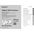
MVC-CD250/CD400
1-1-4. Precaution 1. Setting the Switch Unless otherwise specified, set the switches as follows and perform adjustments.
Yellow
SETUP settings VIDEO OUT (SETUP2) ............................................... NTSC MENU settings 1. WHITE BALANCE ..................................................... AUTO 2. ISO ............................................................................... AUTO 3. IMAGE SIZE ............................ 2272 � 1704 (MVC-CD400) ............................ 1600 � 1200 (MVC-CD250) 4. PICTURE EFFECT ......................................................... OFF 5. EV .......................................................... 0EV (MVC-CD250)
Blue
Cyan
White
Switch settings 1. Mode dial ..................................................... CAMERA ( ) 2. ZOOM (W) ............................................................ WIDE end 3. MACRO ( ) .................................................................. Off 4. FOCUS (PK-65/66 board) *1 ....................................... Manual 5. EV (PK-65/66 board) *1 ................................................... 0EV 6. AE LOCK (PK-65/66 board) *1 ......................................... Off *1 : MVC-CD400 model only
2. Order of Adjustments Basically carry out adjustments in the order given.
Color bar chart (Color reproduction adjustment frame )
H
Green
Electronic beam scanning frame
Magenta Red
C
C=D
D
Magenta Red Blue Yellow
CRT picture frame
V AB A=B BA Enlargement
Cyan Green White
Fig. a Video terminal output waveform
Effective picture frame
Fig. b (monitor TV picture) Difference in level Adjust the camera zoom and direction to obtain the output waveform shown in Fig. a and the TV monitor display shown in Fig. b.
B
A
Fig. 5-1-7
3. 1) Subjects Color bar chart (Color reproduction adjustment frame) When performing adjustments using the color bar chart, adjust the picture frame as shown in Fig. 5-1-7. (Standard picture frame) Clear chart (Color reproduction adjustment frame) Remove the color bar chart from the pattern box and insert a clear chart in its place. (Do not perform zoom operations during this time.) Flange back adjustment chart Make the chart shown in Fig. 5-1-8 using A0 size (1189mm � 841mm) black and white vellum paper.
White 841mm Black
2)
3)
1189mm
Fig. 5-1-8
Note: Use matte vellum paper bigger than A0, and make sure the edges of the black and white paper joined together are not rough.
5-6
|
|
|
> |
|