|
|
|
Kategorie
|
|
Informacje
|
|
Polecamy
|
|
|
 |
|
|
Dla tego produktu nie napisano jeszcze recenzji!
 ;
jedyne do czego mogę mieć zastrzeżenie to jakość zdjęć zawartych w przesłanej instrukcji serwisowej ponieważ są fatalnej jakości, praktycznie nieczytelne. tak poza tym jestem zadowolony to jest to czego szukałem.
 ;
Wszystko w porządku.
Instrukcja czytelna i kompletna.
Dziękuję.
all right!
thank you.
;
Bardzo dobra instrukcja. Zawiera wszystko co potrzeba, polecam!
;
Instrukcja jest OK. Schematy czytelne, opisane niektóre procedury.
;
Instrukcja bardzo czytelna. zawiera co potrzeba. Polecam
NOTE 1. Forced
When across secondmy In order
ON
BEFORE
STARTING ofelectrolytic
REPAIR capacitor ofpower
relay circuit
discharge
is going
supply
in the cord
block
power supply block, Ifrepair electric isattempted potential is kept charged the
repair
to be attempted capacitors (CIO1,
in the 102)
set that even
uses though
theelectrolytic defect to prevent can the
ACpower
is removed.
inthiscondition,
occur. secondary trouble, perform the following measures before starting repair work.
Discharue -.
Remove Connect hasclips wire
wocedure
the AC power cord. resistor Connect at an end theother of lead wire that lead
1,,,
II MAIN C.B
a discharging at both ends.
endofthe
to metal the (+) the
chassis. other side same end (+VH) end (-) seconds) across a multimeter C101 and C102 has decreased of the of discharging (For two resistor seconds) resistor in the as step same to the
Contact positive Contact @) to the way. Check 1V (For
C101.
of the side
discharging of C102
negative two
(-VH)
that or less
voltage using
or an oscilloscope.
I
6
Select
a discharging
resistor
referring
to the
following
table.
Fig-1
Charging
voltage
(V)
Discharging Rated power (W) Parts number resistor 100 220 (Q) 3 5 87-AOO-247-090 87-AOO-232-090
(Clol,
25-48 49-140
102)
Note:
The
reference
numbers
(C101, charging
C102)
of the
electrolytic on schematic
capacitors diagram
can
change
depending the
on the discharging
models. work.
Be
sure
to check
the
reference
numbers
of the
capacitors
before
starting
2.
Check
Be sure
items
to check that
before
the the following
exchanging
items before
the
MICROCOMPUTER
the MICROCOMPUTER. Exchange the MICROCOMPUTER after
exchanging is surely
confirming
MICROCOMPUTER
defective.
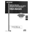
2-1.
Regarding
When correctly. the HOLD the the
the
HOLD When terminal
HOLD
terminal this
terminal
(INPUT) is �L�, exchange. is not the
of the
of the the
MICROCOMPUTER
is �H�, be turned the on. MICROCOMPUTER Therefore, be sure is judged to check the to be operating terminal voltage of
MICROCOMPUTER main power cannot
terminal before
When
MICROCOMPUTER that triggers
defective, detection
the
HOLD circuit
terminal on the
can MAIN
also
go
�L� that
when sets the
the
POWER
AMPLIFIER to �L�.
has
any
abnormalities
abnormality
C. B.
HOLD
terminal
q
Good
or no good
on the that AC the
judgement
main main power. power
of the
MICROCOMPUTER
Turn Confirm not. When
is turned
on
and
the
HOLD
terminal
of the
MICROCOMPUTER
keeps
the
�H�
level
or
the
HOLD
terminal
is �L�
level,
the
abnormality
detection
circuit
is judged
to be working
correctly
and
the
MICROCOMPUTER
is judged
to be good.
�
.�
.�
FRONT
.
C.B
( ; I
r
. ,
.�. � .�-�
MAIN C.B
(
.�-�
I
PIN101 MICROCOMPU~R & o �
I
CON601
In
some
models,
it is PIN
@.
@
OVER
LOAD
DET
POWER
AMP
POWER
AMP
POWER PIN number is different upon microprocessor. .� -�. .� .�. � .�. �.
SUPPLY
depending �.�
I
�-
-
Fig-2-1
�5�
|
|
|
> |
|