|
|
|
Kategorie
|
|
Informacje
|
|
Polecamy
|
|
|
 |
|
|
Dla tego produktu nie napisano jeszcze recenzji!
 ;
...instruction is ok.
...instrukcja jest ok.
Thanks/Dzięki
;
Documentation made available quickly and It is good quality. Thanks.
NOTE ON BEFORE
STARTING
REPAIR
1. Forced discharge ofelectrol~ic capacitor ofpower supply block
When repair is going to be attempted in the set that uses relay circuit in the power supply block, electric potential is kept charged across theelectrolytic capacitors (CIOl, 102) even though ACpower cord is removed. Ifrepair isattempted inthiscondition, the secondary defect can occur. In order to prevent the secondary trouble, perform the following measures before starting repair work.
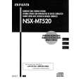
Discharae @ @ Drocedure 1,,,
Remove the AC power cord, Connect a discharging resistor at an end of lead wire that has clips at botb ends. Connect the other end of the lead wire to metal chassis. Contact the other end of the discharging resistor to the positive (+) side (+VH) of C101. (For two seconds) Contact the same end of the discharging resistor as step @)to the negative (-) side (-VH) of CI02 in the same way. (For two seconds) Check that voltage across CIOI and C102 has decreased 1 V or less using a multimeter or an oscilloscope.
I
II MAINC.B
co @
Gil
Select a discharging resistor referring to the following table. ,
Charging voltage (V) Discharging resistor (C?)
Fig-1
(Clol, 102)
25-48
Ratedpower(W)
3 5
Partsnumber
87-AOO-247-090 87-AOO-232-090 I
100
220
I
49-140
Note: The reference numbers (C101, C 102) of the electrolytic capacitors can change depending on the models. Be sure to check the reference numbers of the charging capacitors on schematic diagram before starting the discharging work.
2. Check items before exchanging the MICROCOMPUTER
Be sure to check the following items before exchanging the MICROCOMPUTER. Exchange the MICROCOMPUTER after confirming that the MICROCOMPUTER is surely defective.
2-1. Regarding the HOLD terminal of the MICROCOMPUTER
When the HOLD terminal (INPUT) of the MICROCOMPUTER is �H, the MICROCOMPUTER is judged to be operating correctly. When this terminal is �L�, the main power cannot be turned on. Therefore, be sure to check the terminal voltage of the HOLD terminal before exchange. When the MICROCOMPUTER is not defective, the HOLD terrnimd can also go �L� when the POWER AMPLIFIER has any abnormalities that triggers the abnormality detection circuit on the MAIN C. B. that sets the HOLD terminal to �L�.
q
Good or no goodjudgement of the MICROCOMPUTER @ Turn on the AC main power. @ Confirm that the main power is turned on and the HOLD terminal of the MICROCOMPUTER keeps the �H� level or
not. @ When the HOLD terminal is �L� level, the abnormality detection circuit is judged to be working correctly and the MICROCOMPUTER is judged to be good, �. �.� .
FRONT C.B a
.�.� .�.� .�.� r
i
MAIN C.B
In some models, it is PIN @.
PIN number is different depending upon microprocessor. �.� .
.�. Fig-2-1 -4-
�
.�-�
.�.
�
..
|
|
|
> |
|