|
|
|
Kategorie
|
|
Informacje
|
|
Polecamy
|
|
|
 |
|
|
Dla tego produktu nie napisano jeszcze recenzji!
 ;
Schematy są ale można wysilić się i zrobić kolorowy skan i o większej rozdzielczości. Wtedy schematy płytek będą czytelniejsze. Całość super jako wartość merytoryczna. Wszystkie dane potrzebne do podłączenia różnego rodzajów urządzeń takich gramofon, CD itd.
 ;
Szybko, sprawnie i tanio. Serwis godny polecenia. Będę polecał innym
;
Ogólnie jest OK, z wyjątkiem obrazu płyty głównej, który jest miejscami mało czytelny, ale można sobie poradzić.
;
Dokładna dokumentacja, pomogła w szybkiej naprawie telewizora. Dziękuję!
;
jedyne do czego mogę mieć zastrzeżenie to jakość zdjęć zawartych w przesłanej instrukcji serwisowej ponieważ są fatalnej jakości, praktycznie nieczytelne. tak poza tym jestem zadowolony to jest to czego szukałem.
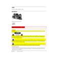
ADJUSTMENT <TUNER / DECK>
u
TUNER
C.B
CN701 TP6 IoGND 2 (LCH)@ @h
\
TP7
(RCH)
TP3
r EEEl-IC771 L771
q
q
TP4
a~
< TUNER
SECTION> 5. FM Tracking Check Settings : q Test point : TP6(Lch), TP7(Rch) Method : Set to FM 98.OMHZ and check that the test point is less than 9. OdBLV. AM IF Adjustment Settings : q Test point: TP6(Lch), TP7(Rch) q Adjustment location : L772 ................................................45O~z Method : Adjust L772 so that the output becomes max. DC Balance/ Mono Distortion Adjustment Settings : q Test point : TP3, TP4 (DC Balance) TP6(Lch), TP7(Rch) (Distortion) q Adjustment location : L771 c Input level : 60dBLV Method : Set to FM 98.OMHZ and adjust L771 so that the voltage between TP3 and TP4 becomes OV t 0.04V. Next, check that the distortion is less than 1.3%
1. Clock Frequency Check Settings : q Test point: TP2 (CLK) Method: Set to AM 1710kHz and check that the test point is 2160kHz t45Hz. 6. 2. AM VT Check Settings : q Test point: TP 1 (VT) Method: Set to AM 1710kHz and AM 530kHz and check that the test point is less than 8.5V(1710kHz) and more than 0.6V(530kHz). 7. 3. AM Tracking Adjustment Settings : q Test point: TP6(Lch), TP7(Rch) q Adjustment location : L981(l/3) ................................ 1000kHz(U) L981(l/3) ................................999kHz(LH) Method : Set to AM 1000kHz(U),999kHz(LH) and adjust L98 1(1/3) so that the test point is max. FM VT Check Settings : q Test point : TP 1 (VT) Method : Set to FM 108.OMHZ and check that the test point is less than 8.OV. Set to FM 87.5MHz and check that the test point is more than 0.5V.
4.
58
|
|
|
> |
|