|
|
|
Kategorie
|
|
Informacje
|
|
Polecamy
|
|
|
 |
|
|
Dla tego produktu nie napisano jeszcze recenzji!
 ;
Dokładna dokumentacja, pomogła w szybkiej naprawie telewizora. Dziękuję!
 ;
jedyne do czego mogę mieć zastrzeżenie to jakość zdjęć zawartych w przesłanej instrukcji serwisowej ponieważ są fatalnej jakości, praktycznie nieczytelne. tak poza tym jestem zadowolony to jest to czego szukałem.
;
Wszystko w porządku.
Instrukcja czytelna i kompletna.
Dziękuję.
all right!
thank you.
;
Bardzo dobra instrukcja. Zawiera wszystko co potrzeba, polecam!
;
Instrukcja jest OK. Schematy czytelne, opisane niektóre procedury.
ELECTRICAL ADJUSTMENT -5/7
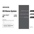
<DECK Section> Make the following preparations for DECK section adjustment. Preparations Measuring Equipment: Audio Signal Generator / Attenuator / Wow and Flutter Meter (Frequency Counter) / Oscilloscope / Millivoltmeter / Dummy resistance (6�) Test Tape: TTA-100 / TTA-300 (or TTA-310, 320) / TTA-200 / TTAA602(or equivalent recording and Playback Test Tapes) 10. Tape Speed Adjustment (DECK 2) Requirements � Measuring instrument: Wow and flutter meter (frequency counter) Test tape: TTA-100 (3 kHz) Test point: HP OUT Adjustment point: SFR1 1) Connect the wow and flutter meter to HP OUT of the unit. 2) Insert the test tape (TTA-100) to DECK 2. Play back the middle part of the tape, and adjust SFR1 so that the level 3,000 Hz 5 Hz is monitored. 11. Tape Speed Check (DECK 1) Requirements: Same as the above, 10. 1) Insert the test tape (TTA-100) to DECK 1. Play back the middle part of the tape, and check that the level is ranged within 55 Hz as compared to the speed monitored for DECK 2. 12. Wow and Flutter Check (DECK 1 and DECK 2) Requirements: Same as the above, 10. 1) Connect the wow and flutter meter to HP OUT of the unit. 2) Set the wow and flutter to JIS for INDICATOR and to W RMS (WTD) for mode. 3) Play back the middle part of the test tape (TTA-100), and check that the level ranges under 0.25%. 13. Head Azimuth Adjustment (DECK 1 and DECK 2) Requirements � Measuring instrument: Oscilloscope Test tape: TTA-300 (10 kHz) Test point: TP8 (Lch), TP9 (Rch) Adjustment point: Head azimuth adjustment screw 1) Connect the probe CH1 of the oscilloscope to TP8 (Lch) and CH2 to TP9 (Rch). 2) Set V mode of the oscilloscope to ADD. 3) Insert the test tape (TTA-300) to DECK 1. Forward and play back the middle part of the tape, and adjust the head azimuth adjustment screw so that the waveform achieves its maximum level when 10 kHz is played. 4) After adjustment, secure the screw with glue (1600 B). 5) Apply the above steps 3) and 4) to DECK 2. 14. Playback Frequency Check (DECK 1 and DECK 2) Requirements � Measuring instrument: Millivoltmeter Test tape: TTA-300 (315 Hz / 10 kHz) Test point: TP8 (Lch), TP9 (Rch) 1) Connect CH1 of the millivoltmeter to TP8 (Lch) and CH2 to TP9 (Rch). 2) Insert the test tape (TTA-300) to DECK 1, and play back 315 Hz and 10 kHz. 3) Check that the level of 10 kHz is ranged within 0 315 Hz as a reference. 4) Apply the above steps 2) and 3) to DECK 2. 3 dB compared to the output level of
TP8 TP9
WOW&FLUTTER METER Hz INPUT HP OUT %
OSCILLOSCOPE
OUTPUT CH1 CH2
AC MILLIVOLTMETER
CH1 CH2 TP8 TP9
-39-
|
|
|
> |
|