|
|
|
Kategorie
|
|
Informacje
|
|
Polecamy
|
|
|
 |
|
|
Dla tego produktu nie napisano jeszcze recenzji!
 ;
jedyne do czego mogę mieć zastrzeżenie to jakość zdjęć zawartych w przesłanej instrukcji serwisowej ponieważ są fatalnej jakości, praktycznie nieczytelne. tak poza tym jestem zadowolony to jest to czego szukałem.
 ;
Wszystko w porządku.
Instrukcja czytelna i kompletna.
Dziękuję.
all right!
thank you.
;
Bardzo dobra instrukcja. Zawiera wszystko co potrzeba, polecam!
;
Instrukcja jest OK. Schematy czytelne, opisane niektóre procedury.
;
Instrukcja bardzo czytelna. zawiera co potrzeba. Polecam
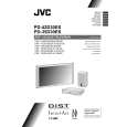
PD-42D30ES
2.5 DISASSEMBLY OF PROCEDURE [RECEIVER UNIT] 2.5.1 REMOVING THE TOP COVER (1) Remove the 4 screws [A] on the both left and right sides. (2) Remove the 3 screws [B] on the rear side. (3) Lift upwards and withdraw the TOP COVER. 2.5.2 REMOVING THE FRONT PANEL � Remove the TOP COVER. (1) Remove the 1 screw [C] and 1 screw [D]. (2) Disengage the 2 claws [E] on the both left and right sides. (3) Disengage the 2 claws [F] on the bottom side. (4) Withdraw the FRONT PANEL in a front direction. 2.5.3 REMOVING THE DAMPER (INSIDE FRONT PANEL) � Remove the TOP COVER. � Remove the FRONT PANEL. (1) Remove the 1 screw [G], and remove the DAMPER. 2.5.4 REMOVING THE FRONT CONTROL PWB � Remove the TOP COVER. � Remove the FRONT PANEL. (1) Remove the 4 screws [H], and remove the FRONT CONTROL PWB. 2.5.5 REMOVING THE REAR COVER � Remove the TOP COVER. (1) Remove the 2 screws [I], and withdraw the AC INLET. (2) Remove the 2 screws [J] and the 2 screws [K], and withdraw the display output terminal. (3) Remove the 16 screws [L], and withdraw the video/audio terminal. (4) Remove the 2 screws [M], 3 screws [N], 1 screw [O], and withdraw the REAR COVER in a rear direction. 2.5.6 REMOVING THE DIST PWB, DIST RELAY PWB, MICOM PWB, MI-COM INTERFACE PWB, AV JACK PWB, AV SW PWB, and SUB TUNER PWB. � Remove the TOP COVER � Remove the REAR COVER. (1) Remove the 1 screw [P], and remove the PB HOLDER. (2) Remove the 2 screws [Q] and 2 screws [R]. (3) Lift upwards and withdraw the SUPPORT BRACKET, the DIST PWB, and the DIST RELAY PWB. (4) Remove the 5 screws [S] and 1 screw [T], and remove the SUPPORT BRACKET. (5) Pull right and left and remove the DIST PWB and the DIST RELAY PWB. (6) Lift upwards and withdraw the MI-COM PWB and the MICOM INTERFACE PWB. (7) Pull right and left and remove the MI-COM PWB and the MI-COM INTERFACE PWB. (8) Remove the 3 screws [U], and remove the TERMINAL BRACKET. (9) Lift upwards and withdraw the AV JACK PWB and the AV SW PWB. (10) Pull right and left and remove the AV JACK PWB and the AV SW PWB. (11) Lift upwards and withdraw the SUB TUNER PWB. 2.5.7 REMOVING THE MAIN PWB AND RECEIVER POWER PWB � Remove the TOP COVER � Remove the REAR COVER. � Remove the DIST PWB, DIST RELAY PWB, MI-COM PWB, MI-COM INTERFACE PWB, AV JACK PWB, AV SW PWB, and SUB TUNER PWB. (1) Remove the 2 screws [V] and 2 screws [W]. Then, lift upwards and withdraw the MAIN PWB. (2) Remove the 6 screws [X], and remove the MI-COM HOLDER and the RECEIVER POWER PWB. 2.5.8 REMOVING THE AC INLET � Remove the TOP COVER � Remove the REAR COVER. (1) Remove the 1 screw [Y], and remove the AC INLET.
(No.52090)1-15
|
|
|
> |
|