|
Dla tego produktu nie napisano jeszcze recenzji!
 ;
Wszystko w porządku.
Instrukcja czytelna i kompletna.
Dziękuję.
all right!
thank you.
;
Bardzo dobra instrukcja. Zawiera wszystko co potrzeba, polecam!
 ;
Instrukcja jest OK. Schematy czytelne, opisane niektóre procedury.
;
Instrukcja bardzo czytelna. zawiera co potrzeba. Polecam
;
...instrukcja serwisowa w pełni czytelna i kompletna. Dziękuję!
5
6
7
8
PD-F1039
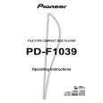
NOTE FOR PCB DIAGRAMS:
1. Part numbers in PCB diagrams match those in the schematic diagrams. 2. A comparison between the main parts of PCB and schematic diagrams is shown below.
Symbol in PCB Diagrams Symbol in Schematic Diagrams Part Name
SIDE A
A
B
C
EB
C
E Transistor
VR151
BCE B BCE C EB C E
Transistor with resistor
D DGS
G
SD
G
S Field effect transistor
Resistor array
3-terminal regulator 3. The parts mounted on this PCB include all necessary parts for several destination. For further information for respective destinations, be sure to check with the schematic diagram.
B
4. Viewpoint of PCB diagrams
Connector Capacitor
SIDE A
P. C. Board
Chip Part
SIDE B
R
HEADPHONE BOARD ASSY
C
(PNP1451-F)
Q
KEY BOARD ASSY
KF
CN702
(PNP1468-B)
D
E J651
B J631
JFQ R
5 6 7 8
13
|