|
|
|
Kategorie
|
|
Informacje
|
|
Polecamy
|
|
|
 |
|
|
Dla tego produktu nie napisano jeszcze recenzji!
 ;
jedyne do czego mogę mieć zastrzeżenie to jakość zdjęć zawartych w przesłanej instrukcji serwisowej ponieważ są fatalnej jakości, praktycznie nieczytelne. tak poza tym jestem zadowolony to jest to czego szukałem.
 ;
Wszystko w porządku.
Instrukcja czytelna i kompletna.
Dziękuję.
all right!
thank you.
;
Bardzo dobra instrukcja. Zawiera wszystko co potrzeba, polecam!
;
Instrukcja jest OK. Schematy czytelne, opisane niektóre procedury.
;
Instrukcja bardzo czytelna. zawiera co potrzeba. Polecam
1
2
3
4
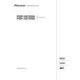
5.1.5 FLOWCHART OF FAILURE ANALYSIS FOR THE MAIN ASSY
A
Flowchart of Failure Analysis for The MAIN Assy
Failure analysis for the MAIN Assy. � MA1
The STB LED does not light although STB 3.3 V power is supplied.
Is the M1 connector securely connected? Yes
No
Securely connect the M1 connector.
B
Is the cable that is connected to the M1 connector broken? No Is resetting of the IF microcomputer canceled? Yes Is the voltage at Pin 1 of the M5 connector high? Yes Is the M5 connector securely connected?
Yes
Replace the cable (J207).
No
Replace the MAIN Assy.
Failure in the RST IC (IC4801) output or its peripheral circuits
No
Replace the MAIN Assy.
Failure in the line between the IF microcomputer and M7 connector
No
Securely connect the M5 connector.
C
Yes Is the cable that is connected to the M5 connector broken? No No problem with the MAIN Assy. Check the LED Assy. Yes Replace the cable (J113).
Failure analysis for the MAIN Assy. � MA2
D
The RELAY port does not work. The power is not turned on.
Is voltage at REQ_IF (3.3 V) on the MAIN Assy high? Yes
No
Can the unit be turned on, using the remote control unit? Yes
No
Can the unit be turned on, using No the Power switch on the main unit? Yes
Replace the cable that connects the SIDE KEY and MAIN Assys. NG Replace the MAIN Assy. NG
Replace the cable that connects the LED IR and MAIN Assys.
NG Replace the cable that connects the LED IR and MAIN Assys. NG
E
Can the unit be turned on, using No the Power switch on the main unit? Yes Replace the cable that connects the SIDE KEY and MAIN Assys.
Replace the LED IR Assy.
NG Replace the cable that connects the SIDE KEY and MAIN Assys. NG Replace the SIDE KEY Assy.
Replace the MAIN Assy. Is the power (1.8 V, 3.3 V) supplied to the main microcomputer? No Replace the MAIN Assy.
� Failure in the REC IC (IC4402) and PM SW (IC4407) outputs � Does the voltage remain low even though it should be active? � A shutdown, indicated by 9 flashes of LED, will be established in 20 seconds.
F
Yes Replace the MAIN Assy.
If the voltage at Pin 129 (RST2 port) on the main microcomputer is high, it is judged that the AC power cord is not plugged in, and operation of the unit will stop there.
82
1 2
PDP-427XD
3 4
|
|
|
> |
|