|
|
|
Kategorie
|
|
Informacje
|
|
Polecamy
|
|
|
 |
|
|
Dla tego produktu nie napisano jeszcze recenzji!
 ;
Dokładna dokumentacja, pomogła w szybkiej naprawie telewizora. Dziękuję!
 ;
jedyne do czego mogę mieć zastrzeżenie to jakość zdjęć zawartych w przesłanej instrukcji serwisowej ponieważ są fatalnej jakości, praktycznie nieczytelne. tak poza tym jestem zadowolony to jest to czego szukałem.
;
Wszystko w porządku.
Instrukcja czytelna i kompletna.
Dziękuję.
all right!
thank you.
;
Bardzo dobra instrukcja. Zawiera wszystko co potrzeba, polecam!
;
Instrukcja jest OK. Schematy czytelne, opisane niektóre procedury.
R-21AM
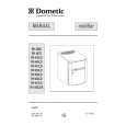
POSITIVE LOCK® CONNECTOR (NO-CASE TYPE) REMOVAL
Terminal
1. CARRY OUT 3D CHECKS. 2. Push the lever of positive lock® connector. 3. Pull down on the positive lock® connector. CAUTION: WHEN CONNECTING THE POSITIVE LOCK® CONNECTORS TO THE TERMINALS, INSTALL THE POSITIVE LOCK ® CONNECTOR SO THAT THE LEVER FACES YOU
Positive lock® connector 1 Push Lever
2 Pull down
Figure C-2 Positive lock® connector
ANTENNA MOTOR REMOVAL
1. Disconnect the oven from the power supply. 2. Remove the one (1) screw holding the base plate cover to the base plate and remove the base plate cover. 3. Disconnect the wire leads from the antenna motor and remove the one (1) screw holding the antenna motor. 4. Remove the antenna motor shaft from the antenna motor. 5. Now, the antenna motor is free.
FAN MOTOR REPLACEMENT
REMOVAL
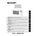
1. CARRY OUT 3D CHECKS. 2. Remove the one (1) screw holding the noise filter to the chassis support. 3. Release the noise filter from the tab on the fan duct. 4. Disconnect the wire leads from the fan motor. 5. Remove the one (1) screw holding the capacitor holder to the oven cavity rear plate. 6. Remove the one (1) screw holding the fan duct to the oven cavity rear plate. 7. Remove the fan duct from the oven. 8. Remove the fan blade from the fan motor shaft according to the following procedure. 9. Hold the edge of the rotor of the fan motor by using a pair of groove joint pliers. CAUTION: * Make sure that no metal pieces enter the gap between the rotor and the stator of the fan motor because the rotor is easily shaven by pliers and metal pieces may be produced. * Do not touch the pliers to the coil of the fan motor because the coil may be cut or injured. * Do not disfigure the bracket by touching with the pliers. 10.Remove the fan blade from the shaft of the fan motor by pulling and rotating the fan blade with your hand. 11. Now, the fan blade will be free. CAUTION: * Do not reuse the removed fan blade because the hole (for shaft) may be larger than normal. 12.Remove the two (2) screws holding the fan motor to the fan duct. 13.Now, the fan motor is free. INSTALLATION 1. Install the fan motor to the fan duct with the two (2) screws. 2. Install the fan blade to the fan motor shaft according to the following procedure. 3. Hold the center of the bracket which supports the shaft of the fan motor on the flat table. 4. Install the fan blade to the shaft of fan motor by pushing the fan blade with a small, light weight, ball peen hammer or rubber mallet. CAUTION: * Do not hit the fan blade hard when installing because the bracket may be disfigured. * Make sure that the fan blade rotates smooth after installation. * Make sure that the axis of the shaft is not slanted. 5. Install the fan duct to the oven cavity rear plate with the one (1) screw. 6. Install the capacitor holder to the oven cavity rear plate with the one (1) screw. 7. Install the noise filter to the fan duct and the chassis support with the one (1) screw. 8. Re-connect the wire leads to the fan motor.
Coil Groove joint pliers
Shaft
Stator Gap Bracket Rotor
Shaft Axis Stator Rotor
These are the positions that should be pinched with pliers Table
Center of bracket
Rear view
Side view
21
|
|
|
> |
|