|
Dla tego produktu nie napisano jeszcze recenzji!
 ;
Dokładna dokumentacja, pomogła w szybkiej naprawie telewizora. Dziękuję!
 ;
jedyne do czego mogę mieć zastrzeżenie to jakość zdjęć zawartych w przesłanej instrukcji serwisowej ponieważ są fatalnej jakości, praktycznie nieczytelne. tak poza tym jestem zadowolony to jest to czego szukałem.
;
Wszystko w porządku.
Instrukcja czytelna i kompletna.
Dziękuję.
all right!
thank you.
;
Bardzo dobra instrukcja. Zawiera wszystko co potrzeba, polecam!
;
Instrukcja jest OK. Schematy czytelne, opisane niektóre procedury.
2.9
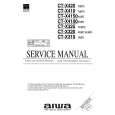
Removing the heat sink (See Figs.10 and 11)
� Prior to performing the following procedures, remove the top cover and main board. (1) From the reverse side of the main board, remove the two screws P attaching the main board to the heat sink. (See Fig.10.) (2) Disconnect the connectors (CN701-CN706) on the main board, remove the main board. (See Fig.10.) (3) Remove the twelve screws Q attaching the heat sink. (See Fig.11.)
Heat sink
Main board
P
P
CN706 CN703 CN701 CN702 CN704 Fig.10 CN705
Heat sink
Q
Q
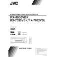
Fig.11 2.10 emoving the center board, surround back board, front amp. boards (L/R) and rear amp. boards (L/R) (See Figs.10 and 12) � Prior to performing the following procedures, remove the top cover and main board. (1) From the reverse side of the main board, remove the two screws P attaching the main board to the heat sink. (See Fig.10.) (2) Disconnect the connectors (CN701-CN706) on the main board, remove the main board. (See Fig.10.) (3) Remove the two screws Q attaching the center board. (See Fig.12.) (4) Remove the two screws Q attaching the front board(L). (See Fig.12.) (5) Remove the two screws Q attaching the surround back board. (See Fig.12.) (6) Remove the two screws Q attaching the front board(R). (See Fig.12.) (7) Remove the two screws Q attaching the surround board(L). (See Fig.12.) (8) Remove the two screws Q attaching the surround board(R). (See Fig.12.)
Front board(R)
Front board(L)
Q
Q
Q
Q
Q
Q
Surround board(R)
Surround board Surround board(L) Center board Fig.12
1-8 (No.22058)
|