|
|
|
Kategorie
|
|
Informacje
|
|
Polecamy
|
|
|
 |
|
|
Dla tego produktu nie napisano jeszcze recenzji!
 ;
Dokładna dokumentacja, pomogła w szybkiej naprawie telewizora. Dziękuję!
 ;
jedyne do czego mogę mieć zastrzeżenie to jakość zdjęć zawartych w przesłanej instrukcji serwisowej ponieważ są fatalnej jakości, praktycznie nieczytelne. tak poza tym jestem zadowolony to jest to czego szukałem.
;
Wszystko w porządku.
Instrukcja czytelna i kompletna.
Dziękuję.
all right!
thank you.
;
Bardzo dobra instrukcja. Zawiera wszystko co potrzeba, polecam!
;
Instrukcja jest OK. Schematy czytelne, opisane niektóre procedury.
SA-HT440P / SA-HT440PC
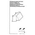
Step 1 Remove the 2 screws. Step 2 Remove the tray base guide (L) and tray guide (R) in the direction of arrow. Note: Refer to the diagrams of Power P.C.B. (Section 19.3) for location of the parts.
10.14. Disassembly of Switch Regulator IC (IC5701)
· Follow (Step 1) to (Step 6) of Item 10.11. Step 1 Desolder all pins of IC5701. Step 2 Desolder 2 pins of Switch Regulator IC. Step 3 Remove the Switch Regulator IC.
10.16. Disassembly of the Rotary Tray
· Follow (Step 1) to (Step 3) of Item 10.5.
Step 1 Remove tray screw and tray spring. Step 2 Remove rotary tray.
Note: Refer to the diagrams of Power P.C.B. (Section 19.3) for location of the parts. Caution: Be careful when removing the Switch Regulator IC which has high temperature after prolonged use.
10.16.1. Disassembly of the Open Lock Gear
10.15. Disassembly of the Tray Base Guide (L) and Tray Base Guide (R)
· Follow (Step 1) to (Step 3) of Item 10.5.
Step 1 Rotate open lock gear in the direction of arrow. (Anticlockwise)
36
|
|
|
> |
|