|
|
|
Kategorie
|
|
Informacje
|
|
Polecamy
|
|
|
 |
|
|
Dla tego produktu nie napisano jeszcze recenzji!
 ;
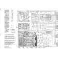
Schematy są ale można wysilić się i zrobić kolorowy skan i o większej rozdzielczości. Wtedy schematy płytek będą czytelniejsze. Całość super jako wartość merytoryczna. Wszystkie dane potrzebne do podłączenia różnego rodzajów urządzeń takich gramofon, CD itd.
 ;
Szybko, sprawnie i tanio. Serwis godny polecenia. Będę polecał innym
;
Ogólnie jest OK, z wyjątkiem obrazu płyty głównej, który jest miejscami mało czytelny, ale można sobie poradzić.
;
Dokładna dokumentacja, pomogła w szybkiej naprawie telewizora. Dziękuję!
;
jedyne do czego mogę mieć zastrzeżenie to jakość zdjęć zawartych w przesłanej instrukcji serwisowej ponieważ są fatalnej jakości, praktycznie nieczytelne. tak poza tym jestem zadowolony to jest to czego szukałem.
SH-FX60PP / SH-FX60TPP / SE-FX60PP
Step 2 : Detach the flat wire from the ribs of rear cabinet. (Ensure during assembly, the flat wire must be properly dressed in between the 2 supporting ribs.) Step 3 : Detach connector CN1003. Step 4 : Remove Receiver Module P.C.B. as arrow shown. Caution : Avoid applying excessive force. Use anti-static strap when removing the Receiver Module P.C.B. Step 1 : Remove Heat Sink Clip as arrow shown.
7.7.
Disassembly of Digital Amp P.C.B.
· Follow the (Step 1) - (Step 3) of item 7.4. · Follow the (Step 1) - (Step 2) of item 7.6.
Step 2 : De-solder digital Amp IC and remove Insulator IC. Note: During assembly, after replacement of new digital Amp IC installation of insulator needed.
7.9.
Disassembly of SMPS Module Unit
· Follow the (Step 1) - (Step 3) of item 7.4. Step 1 : Detach flat cabl (CN2). Step 2 : Remove Digital Amp P.C.B. as arrow shown. · Follow the (Step 1) - (Step 2) of item 7.6.
7.8.
Disassembly of Digital Amp IC
· Follow the (Step 1) - (Step 3) of item 7.4. · Follow the (Step 1) - (Step 2) of item 7.6. · Follow the (Step 1) - (Step 2) of item 7.7.
21
|
|
|
> |
|