|
Dla tego produktu nie napisano jeszcze recenzji!
 ;
Schematy są ale można wysilić się i zrobić kolorowy skan i o większej rozdzielczości. Wtedy schematy płytek będą czytelniejsze. Całość super jako wartość merytoryczna. Wszystkie dane potrzebne do podłączenia różnego rodzajów urządzeń takich gramofon, CD itd.
 ;
Szybko, sprawnie i tanio. Serwis godny polecenia. Będę polecał innym
;
Ogólnie jest OK, z wyjątkiem obrazu płyty głównej, który jest miejscami mało czytelny, ale można sobie poradzić.
;
Dokładna dokumentacja, pomogła w szybkiej naprawie telewizora. Dziękuję!
;
jedyne do czego mogę mieć zastrzeżenie to jakość zdjęć zawartych w przesłanej instrukcji serwisowej ponieważ są fatalnej jakości, praktycznie nieczytelne. tak poza tym jestem zadowolony to jest to czego szukałem.
1
2
3
4
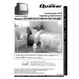
1. REASSEMBLY AND DISASSEMBLY PRECAUTIONS
A
� The grille is inserted into the baf�e. To detach it, insert a grill removal tool into each of the 4 corner holes of the grille net and pull it out carefully. � The subframe is attached to the baf�e frame by 4 external screws. To detach it, unfasten those screws. (for IW631 and IW651) � The crossover networks is attached to the baf�e frame by 4 external screws. To detach them, �rst disconnect the speaker's wires. Next remove the baf�e frame. Then unfasten those screws.
B
� The tweeter is attached to the baf�e by 2 external screws. To detach it, unfasten those screws. When re-attaching it, face its terminal rightward. [S-IW631-LR, S-IW831-LR only] � The woofer is attached to the baf�e by 4 external screws. To detach it, unfasten those screws. When re-attaching it, face its terminal lower right. � Attach the speaker frame to the wall /ceiling, and tighten the screws lightly (temporary attachment). At this point the rotating clamp will rotate so that the rotating clamp and frame are clamped on to the wall/ceiling. Gently try pulling the speaker forward and check that all of the rotating clamps have rotated outwards and are lightly clamping to the wall/ceiling. Speaker frame Screw
C
Rotating clamp
D
� Tighten the screws �rmly using no more than the maximum torque speci�ed. Allowable maximum torque: 1.0 N.m
E
F
2
1 2
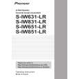
S-IW631-LR
3 4
|