|
|
|
Kategorie
|
|
Informacje
|
|
Polecamy
|
|
|
 |
|
|
Dla tego produktu nie napisano jeszcze recenzji!
 ;
Dokładna dokumentacja, pomogła w szybkiej naprawie telewizora. Dziękuję!
 ;
jedyne do czego mogę mieć zastrzeżenie to jakość zdjęć zawartych w przesłanej instrukcji serwisowej ponieważ są fatalnej jakości, praktycznie nieczytelne. tak poza tym jestem zadowolony to jest to czego szukałem.
;
Wszystko w porządku.
Instrukcja czytelna i kompletna.
Dziękuję.
all right!
thank you.
;
Bardzo dobra instrukcja. Zawiera wszystko co potrzeba, polecam!
;
Instrukcja jest OK. Schematy czytelne, opisane niektóre procedury.
3.3
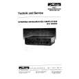
Removing the power cord (See Figs.4 and 5)
� Prior to performing the following procedures, remove the back panel. (1) Remove the two screws C attaching the bracket a. (See Fig.4.) (2) Pull out the bracket a toward you. (3) Disconnect the power cord from the connector CN901 on the power switch board. (See Fig.5.) 3.4 Removing the amplifier board assembly (Amp board, volume board, switch board) (See Figs.5 and 6)
Bracket a
C
Power cord
� Prior to performing the following procedures, remove the back panel and the power cord. � Remove the amplifier assembly from the main body as required. (See Figs.1 and 2.) (1) Remove the three screws D attaching the bracket b. (See Fig 5.) (2) Disconnect the wire from the connectors CN102 and CN503 on the amp board. (See Fig.5.) (3) Remove the amplifier board assembly from the connectors CN951 and CN952 on the regulator board. (See Fig.6.) (4) Take out the amplifier board assembly. 3.5 Removing the power supply board assembly (Regulator board, power switch board) (See Fig.6)
C
Fig.4
Bracket b CN503 CN102
Volume board
D
D
� Prior to performing the following procedures, remove the back panel, power cord and amplifier board assembly. � Remove the amplifier assembly from the main body as required. (See Figs.1 and 2.) (1) Remove the screw E attaching the bracket c. (See Fig.6.) (2) Remove the two screws F and four screws G attaching the regulator board. (3) Take out the power supply board assembly.
Amp board
CN901
Switch board
Power switch board Fig.5
F
Regulator board
CN952 CN951
G E
Power switch board
Fig.6
G
Bracket c
(No.MB251)1-7
|
|
|
> |
|