|
Dla tego produktu nie napisano jeszcze recenzji!
 ;
Schematy są ale można wysilić się i zrobić kolorowy skan i o większej rozdzielczości. Wtedy schematy płytek będą czytelniejsze. Całość super jako wartość merytoryczna. Wszystkie dane potrzebne do podłączenia różnego rodzajów urządzeń takich gramofon, CD itd.
 ;
Szybko, sprawnie i tanio. Serwis godny polecenia. Będę polecał innym
;
Ogólnie jest OK, z wyjątkiem obrazu płyty głównej, który jest miejscami mało czytelny, ale można sobie poradzić.
;
Dokładna dokumentacja, pomogła w szybkiej naprawie telewizora. Dziękuję!
;
jedyne do czego mogę mieć zastrzeżenie to jakość zdjęć zawartych w przesłanej instrukcji serwisowej ponieważ są fatalnej jakości, praktycznie nieczytelne. tak poza tym jestem zadowolony to jest to czego szukałem.
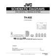
3.1.6 Removing the DSP board (See Figs.9 and 10) � Prior to performing the following procedures, remove the top panel and rear cover. (1) From the top side of the DSP board, disconnect the card wires from the connectors CN401 on the DSP board. (See Fig.10) (2) Remove the screw K attaching the DSP board from the section d of the barrier. (See Fig.10) (3) From the back side of the main body, remove the screw L and two screws M attaching the DSP board. (See Fig.9) Reference: � When attaching the DSP board, hang the DSP board on the section d of the barrier. (See Fig.10)
L
M
N
Fig.9
Rear panel
Section d
3.1.7 Removing the tuner (See Figs.9 and 11) � Prior to performing the following procedures, remove the top panel, rear cover and DSP board. (1) From the top side of the tuner, disconnect the card wire from the connector CN1 on the tuner. (See Fig.11) (2) From the back side of the main body, remove the two screws N attaching the tuner. (See Fig.9) (3) Take out the tuner from the main body.
K
CN401
DSP board
Fig.10
Tuner
Fig.11
CN1
(No.MB055)1-9
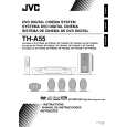
 $4.99 TH-A55 JVC
Schematy Zestaw schematów dla tego urządzenia. Plik PDF zawierający schematy będzie dostarczony na Twó…  $4.99 TH-A55 JVC
Katalog Części Katalog części w formie pliku PDF. Plik zawiera wykaz części znajdujących się w urządzeniu wr…
|