|
Dla tego produktu nie napisano jeszcze recenzji!
 ;
Dokładna dokumentacja, pomogła w szybkiej naprawie telewizora. Dziękuję!
 ;
jedyne do czego mogę mieć zastrzeżenie to jakość zdjęć zawartych w przesłanej instrukcji serwisowej ponieważ są fatalnej jakości, praktycznie nieczytelne. tak poza tym jestem zadowolony to jest to czego szukałem.
;
Wszystko w porządku.
Instrukcja czytelna i kompletna.
Dziękuję.
all right!
thank you.
;
Bardzo dobra instrukcja. Zawiera wszystko co potrzeba, polecam!
;
Instrukcja jest OK. Schematy czytelne, opisane niektóre procedury.
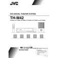
3.3.4 Removing the mother board (See Figs.7 to 9) � Remove the rear panel. � Remove the amplifier assembly. � Remove the speaker terminal board. (1) From the inside of the amplifier assembly, disconnect the wire from the connector CN151 on the mother board. (See Fig.7.) (2) Remove the five screws G attaching the mother board. (See Fig.7.) (3) Take out the mother board together the amplifier boards (A,B) and heat sink. (4) Remove the four screws H attaching the mother board. (See Fig.8.) (5) Release the claws a and b of the connectors (CN521, CN522, CN531, CN532) on the mother board using the flat-bladed screwdriver or a similar tool, disconnect the mother board from the connectors (CN251, CN252, CN351, CN352) on the amplifier boards (A, B). (See Fig.9.) Note: When releasing the claws a and b of the connectors (CN521, CN522, CN531, CN532) on the mother board, be careful not to break the claws of the connectors.
Amplifier board (B)
H
Amplifier board (A)
CN532 CN521
CN531 CN522
Mother board
H
Fig.8
Mother board
Amplifier assembly
CN532 CN531 CN352 CN351 CN151 Claws b Mother board CN251
CN521 CN522
Claws a CN252
G
G
Fig.7
Amplifier board (B)
Heat sink Amplifier board (A) Fig.9
(No.MB067)1-29
|