|
|
|
Kategorie
|
|
Informacje
|
|
Polecamy
|
|
|
 |
|
|
Dla tego produktu nie napisano jeszcze recenzji!
 ;
jedyne do czego mogę mieć zastrzeżenie to jakość zdjęć zawartych w przesłanej instrukcji serwisowej ponieważ są fatalnej jakości, praktycznie nieczytelne. tak poza tym jestem zadowolony to jest to czego szukałem.
 ;
Wszystko w porządku.
Instrukcja czytelna i kompletna.
Dziękuję.
all right!
thank you.
;
Bardzo dobra instrukcja. Zawiera wszystko co potrzeba, polecam!
;
Instrukcja jest OK. Schematy czytelne, opisane niektóre procedury.
;
Instrukcja bardzo czytelna. zawiera co potrzeba. Polecam
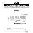
3.1.9 Removing the connect board (See Fig.14) � Remove the metal cover. � Remove the front panel assembly. (1) From the inside of the front panel assembly, disconnect the card wire from the connector CN561 on the connect board. (2) Remove the screw V attaching the support board. (3) Take out the connect board. 3.1.10 Removing the phone jack board (See Fig.14) � Remove the metal cover. � Remove the front panel assembly. (1) From the inside of the front panel assembly, remove the two screws W attaching the phone jack board. (2) Take out the phone jack board.
Phone jack board
W
CN561
Connect board
W V
Card wire
Support board
Fig.14
3.1.11 Removing the operation board (See Fig.15) � Remove the metal cover. � Remove the front panel assembly. � Remove the support board. (1) Remove the two screws X attaching the operation board. (2) Take out the operation board together the Button(top). Reference: Remove the Button(top) from the front board as required. 3.1.12 Removing the front board (See Figs.15 and 16) � Remove the metal cover. � Remove the front panel assembly. � Remove the connect board. � Remove the operation board. (1) From the front side of the front panel assembly, pull out the volume knob. (See Fig.16.) (2) Remove the screw Y attaching the front board. (See Fig.16.) (3) From the inside of the front panel assembly, remove the eight screws Z attaching the front board. (See Fig.15.) (4) Take out the front board while releasing the claws e in the direction of the arrow. (See Fig.15.)
Front board
X Z
Operation board Button(top)
Z
Claws e
Fig.15
Z
Front panel assembly
Y
Volme knob
Fig.16
(No.MB033)1-13
 $4.99 TH-M45 JVC
Schematy Zestaw schematów dla tego urządzenia. Plik PDF zawierający schematy będzie dostarczony na Twó… 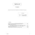 $4.99 TH-M45 JVC
Katalog Części Katalog części w formie pliku PDF. Plik zawiera wykaz części znajdujących się w urządzeniu wr…
|
|
|
> |
|