|
Dla tego produktu nie napisano jeszcze recenzji!
 ;
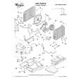
jedyne do czego mogę mieć zastrzeżenie to jakość zdjęć zawartych w przesłanej instrukcji serwisowej ponieważ są fatalnej jakości, praktycznie nieczytelne. tak poza tym jestem zadowolony to jest to czego szukałem.
 ;
Wszystko w porządku.
Instrukcja czytelna i kompletna.
Dziękuję.
all right!
thank you.
;
Bardzo dobra instrukcja. Zawiera wszystko co potrzeba, polecam!
;
Instrukcja jest OK. Schematy czytelne, opisane niektóre procedury.
;
Instrukcja bardzo czytelna. zawiera co potrzeba. Polecam
(1) Monitor the waveform at the test point �TP-G�. (2) Click the [WMB] button and adjust to the specified level. (3) Check the voltage at the test points �TP-R� and �TP-B�. 2 (4) Click [Next] button. [Note] �G� and �B� levels also change when the [WMB] adjustment is performed. Recommendation value : E8 (min:E0 � max:F5) Input Signal : RGB flicker pattern (1) Select a red single color screen when adjusting R. Click the [WM6] button, and adjust the flicker level to minimum in both + and � directions, taking note of the data values. Then set data to the mid-point between the two previously noted values. (2) Adjust other colors to be the same, using [WM5] for green and [WM4] for blue. (3) Click the [Upside Down] button to change projection mode. (4) Adjust this mode in the same way. (5) Click [Next] buttons. Recommendation value : 40 � 50
3
(1) Monitor the waveform at test point �TP-R�. (2) Click the [W03] button and adjust to the specified level. 4 (3) Click [Next] button. [Note] A signal level rises when [�] is pushed. A signal level falls down when [+] is pushed.
(1) Monitor the waveform at test point �TP-G�. (2) Click the [W04] button and adjust to the specified level. 5 (3) Click [Next] button.
1-35
TLPB2 Service Manual Rev. 2.0
|