|
Dla tego produktu nie napisano jeszcze recenzji!
 ;
jedyne do czego mogę mieć zastrzeżenie to jakość zdjęć zawartych w przesłanej instrukcji serwisowej ponieważ są fatalnej jakości, praktycznie nieczytelne. tak poza tym jestem zadowolony to jest to czego szukałem.
 ;
Wszystko w porządku.
Instrukcja czytelna i kompletna.
Dziękuję.
all right!
thank you.
;
Bardzo dobra instrukcja. Zawiera wszystko co potrzeba, polecam!
;
Instrukcja jest OK. Schematy czytelne, opisane niektóre procedury.
;
Instrukcja bardzo czytelna. zawiera co potrzeba. Polecam
TU-65GD1E LC-65GD1E
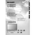
13. Remove the 2 lock screws w and detach the Control Button Ass'y. 14. Remove the 3 lock screws e and detach the Key PWB. 15-1. Remove the 38 Lamp Ass'y lock screws 14-1 and 2 Stand lock screws 14-2 . Draw out the lower side of the Front Cabinet, detach the 2 hook of the engagement of the upper part, and detach the Front Cabinet. 15-2. Detach the Lamp Ass'y from the Stand. 16. Remove the 2 lock screws t and detach the R/C, LED PWB.
14-1
12 13
Key PWB Control Button Ass�y
14-2
Lamp Ass�y
Front Cabinet 15 R/C, LED PWB
17
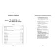
17. Remove 4 FPC y from T-CON Top PWB and T-CON Bottom PWB. 18. Remove 12 lock screws u and detach the PWB Ass'y. 19. Remove the 36 lead wire from Lamps i and detach the 4 B to B connectors of each INVERTER PWB.
B to B 18
16 FPC
PWB Ass'y 18
16 FPC
B to B
21
 $4.99 TU-65GD1E SHARP
Schematy Zestaw schematów dla tego urządzenia. Plik PDF zawierający schematy będzie dostarczony na Twó…
|