|
|
|
Kategorie
|
|
Informacje
|
|
Polecamy
|
|
|
 |
|
|
Dla tego produktu nie napisano jeszcze recenzji!
 ;
Bardzo dobra jakość skanu, przystępna cena. Instrukcja serwisowa okazała się przydatna przy "reanimowaniu" dwudziestoparoletniego decka, który teraz pięknie gra :)
;
...instruction is ok.
...instrukcja jest ok.
Thanks/Dzięki
;
Documentation made available quickly and It is good quality. Thanks.
TOP
FOR SAFETY
DISASSEMBLY
FRAME HARNESS
EXPLODED VIEW
PARTS LIST
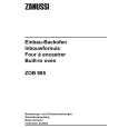
DISASSEMBLY
8
8 REAR COVER ASSY, SWX-184, ANNTENA (RF), RECEIVER (RF)
(*1) (*3)
3
Antenna (RF) Detents
SWX-184 board
1 Remove the seven screws. Ref. No 170
+B 3X4 2-067-023-01 Black
RF bracket
To Flowchart
5
2 Disengage the total 20 detents. Close the PC . card door. While the PC card door is kept closed, remove the rear cover assy. 3 Remove the screw and remove the RF bracket.
Rear cover assy
4
1
Ref. No 167 +PS (3X6) 4-679-053-01 Silver
(*2)
PC card door
Detents
RF bracket
3
Receiver (RF) Detents
2 4
4 Disconnect the connector and disengage the two detents, then remove the antenna (RF) (*1) or receiver (RF) (*2) from the RF bracket. 5 Remove the screw and remove the SWX-184 board (*3).
Ref. No 167 +PS (3X6) 4-679-053-01 Silver
(*1) V517G/V617G Model only (*2) V520G/V620G Model only (*3) V520G/V617G/V620G Model only
� 11 �
|
|
|
> |
|