|
|
|
Kategorie
|
|
Informacje
|
|
Polecamy
|
|
|
 |
|
|
Dla tego produktu nie napisano jeszcze recenzji!
 ;
Dokładna dokumentacja, pomogła w szybkiej naprawie telewizora. Dziękuję!
 ;
jedyne do czego mogę mieć zastrzeżenie to jakość zdjęć zawartych w przesłanej instrukcji serwisowej ponieważ są fatalnej jakości, praktycznie nieczytelne. tak poza tym jestem zadowolony to jest to czego szukałem.
;
Wszystko w porządku.
Instrukcja czytelna i kompletna.
Dziękuję.
all right!
thank you.
;
Bardzo dobra instrukcja. Zawiera wszystko co potrzeba, polecam!
;
Instrukcja jest OK. Schematy czytelne, opisane niektóre procedury.
5
6
7
8
A
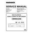
USB Troubleshooting
Step 1: Connectors
CN701, CN702 Are the connectors securely inserted ? Yes To STEP 2 The output and GND may be short-circuited. Check the path between them.
6
IC703 (pin 1), IC702 (pin 7)
3.3 V Reg. output / 1.8 V Reg. input Is IC703 abnormally hot? Yes No
No Insert the connectors securely.
Is the voltage 3.3 V ? Yes
No
Replace IC703.
B
Step 2: Power supply
1
CN702 (pin 4) 5 V input Is there any loose connection of CN702? Yes
7
IC762 (pins 37, 47) FLASH ROM
Is the voltage 5V? Yes
No
No
Is the voltage 3.3 V ? Yes
No
Check the parts and patterns in the path.
Check the MOTHER Assy.
8
C
IC761 (pins 1,3,9,14,27,43,49) SDRAM
To STEP 1
2
IC703 (pin 3)
3.3 V Regulator IC input
Is the voltage 3.3 V ? Yes
No
Check the parts and patterns in the path.
Is the voltage 5V? Yes
No
Check the patterns in the path.
9
IC953 (pin 14) Is the voltage 3.3 V ? Yes
5-3 Converter
No
Check the parts and patterns in the path.
D
3
IC951 (pin 14)
3-5 Converter
Is the voltage 5V? Yes
No
Check the parts and patterns in the path.
10 IC701 (pins 16,33,64,76,112) USB Media control IC
Is the voltage 3.3 V ? Yes
No
Check the parts and patterns in the path.
4
IC771 (pin 5)
USB Power SW
Is the voltage 5V? Yes
No
Check the parts and patterns in the path.
E
11
IC702 (pin 1)
1.8 V Regulator output
5 IC7814 (pins 14, 15) DAC
Is the voltage 5V? Yes No Check the parts and patterns in the path.
Is the voltage 1.8 V ? Yes
No
Is IC702 abnormally hot? Yes
No
Replace IC702.
The output and GND may be short-circuited. Check the path between them.
F
A
VSX-1016V-K
5 6 7 8
131
|
|
|
> |
|