GTX2 Ilość: 1
$4.99
» Pokaż Szczegóły
LBB320300 Ilość: 1
$4.99
» Pokaż Szczegóły
28PW9617/12 Ilość: 1
$4.99
» Pokaż Szczegóły
28PT7106/19R Ilość: 1
$4.99
» Pokaż Szczegóły
KV28WS3D Ilość: 1
$4.99
» Pokaż Szczegóły
P372101TR Ilość: 1
$4.99
» Pokaż Szczegóły
CT8598/00SBASIA Ilość: 1
$4.99
» Pokaż Szczegóły
5005VW Ilość: 1
$4.99
» Pokaż Szczegóły
RHQ10 Ilość: 1
$4.99
» Pokaż Szczegóły
ED2PHEXNB01 Ilość: 1
$4.99
» Pokaż Szczegóły
HOO B01 S Ilość: 1
$4.99
» Pokaż Szczegóły
SIE515GM Ilość: 1
$4.99
» Pokaż Szczegóły
LHT-6240 Ilość: 1
$4.99
» Pokaż Szczegóły
SK 2012 TV Ilość: 1
$4.99
» Pokaż Szczegóły
SCAK323 Ilość: 1
$4.99
» Pokaż Szczegóły
AKL 791/NE Ilość: 1
$4.99
» Pokaż Szczegóły
JEC3461W Ilość: 1
$4.99
» Pokaż Szczegóły
AGS 504/WP Ilość: 1
$4.99
» Pokaż Szczegóły
HA800 Ilość: 1
$4.99
» Pokaż Szczegóły
70FA44305S Ilość: 1
$4.99
» Pokaż Szczegóły
GB2SHTXTB00 Ilość: 1
$4.99
» Pokaż Szczegóły
FAV64062I-M Ilość: 1
$4.99
» Pokaż Szczegóły
AWV 800 Ilość: 1
$4.99
» Pokaż Szczegóły
SA4111/37B Ilość: 1
$4.99
» Pokaż Szczegóły
WJ-FS116 Ilość: 1
$4.99
» Pokaż Szczegóły
KESH307HWH5 Ilość: 1
$4.99
» Pokaż Szczegóły
CFS 610 S Ilość: 1
$4.99
» Pokaż Szczegóły
TC-266 Ilość: 1
$4.99
» Pokaż Szczegóły
KSRD22FKBT14 Ilość: 1
$4.99
» Pokaż Szczegóły
YKGST307HS5 Ilość: 1
$4.99
» Pokaż Szczegóły
TRKK 6950 Ilość: 1
$4.99
» Pokaż Szczegóły
CR5070 Ilość: 1
$4.99
» Pokaż Szczegóły
AWT1056AA Ilość: 1
$4.99
» Pokaż Szczegóły
DIGIVISION5581 Ilość: 1
$4.99
» Pokaż Szczegóły
W sumie: $169.66
 
English Polski Spanish 
Szukaj instrukcji do
 

(e.g. AA-V20EG JVC, ZX-7 Sony )
PayPal 1000+ rating Secure, Encrypted Checkout.
 
Kategorie
Informacje
Polecamy
Strona główna >> SONY >> WMEX678 Instrukcja Serwisowa
 
 34 szt. w koszyku 

SONY WMEX678
Instrukcja Serwisowa


Tweetnij o tym produkcie a dostaniesz $1.00 rabatu!
  • Zawiera schematy
  • Plik do pobrania
  • Format PDF
  • Kompletna instrukcja
  • Język: English
Cena: $4.99

Opis SONY WMEX678 Instrukcja Serwisowa

Kompletna instrukcja serwisowa w formie pliku PDF. Instrukcje serwisowe zazwyczaj zawierają schematy, diagramy drukowanych obwodów (PCB), schematy połączeń, schematy blokowe oraz katalog części. Instrukcje serwisowe są wykorzystywane glównie przez osoby naprawiające uszkodzony sprzęt.

Jeśli chcesz się dowiedzieć jak się obsługuje Twój telewizor, magnetowid, odtwarzacz mp3 itp. powinieneś raczej szukać instrukcji obsługi

Instrukcja jest dostępna w następujących językach: English

Plik nie jest jeszcze gotowy
Musisz najpierw dokonać zakupu.

Recenzje produktu
Dla tego produktu nie napisano jeszcze recenzji!
Recenzje innych produktów
 SA-A30E AIWA Instrukcja Serwisowa by Adam Grążka;
Wszystko w porządku. Instrukcja czytelna i kompletna. Dziękuję. all right! thank you.
 KX990SR KENWOOD Instrukcja Serwisowa by Viktor Kapeć;
Bardzo dobra instrukcja. Zawiera wszystko co potrzeba, polecam!
 TA2760 ONKYO Instrukcja Serwisowa by Viktor Kapeć;
Instrukcja jest OK. Schematy czytelne, opisane niektóre procedury.
 26PF3302/10 PHILIPS Instrukcja Serwisowa by Ryszard Burzak;
Instrukcja bardzo czytelna. zawiera co potrzeba. Polecam
 DX666 AIWA Instrukcja Serwisowa by Adam Grążka;
...instrukcja serwisowa w pełni czytelna i kompletna. Dziękuję!

Tekstowy podgląd strony 3 (kliknij aby zobaczyć)
SECTION 1 SERVISE NOTE
[Service Mode]
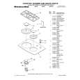
The service mode enables to operate the mechanism of WM-EX678 while the MAIN board is opened. Rotation of the idler gear (A) (S side) is detected using the photoreflector (PH701) in the WM-EX678. PH701 is located on the MAIN board, therefore the rotation of the idler gear (A) (S side) cannot be detected by PH701 when the MAIN board is removed. As a result, the motor cannot be controlled and cannot run correctly. To repair the machine after the MAIN board is removed while the main power is turned on, follow the procedures as described below. 1. Setting 1) Remove the cabinets referring to section �3. DISASSEMBLY�. Open the MAIN board. 2) Connect the motor (M901) and the plunger solenoid (PM901) to the MAIN board using the jumper wires. When the extension jig (1-769-143-11) (10 wires as a set) is used, they can be connected easily. 3) Short the TAPE DETECT switch (S901-1) and the ATS switch (S901-2). 4) Connect an AF oscillator to TP53 (P. IN) and TP14 (GND). 5) Connect DC 1.3 V from external regulated power supply to � and � terminals of the battery. 2. PRE-SET status The PLAY, FF and REW modes can be entered only from the PRESET status. 1) Check that the slider (NR) is in the center position (S701), and the FWD/REV switch is also in the center position. When these switches are not in the center position, set them to the PRE-SET status as follows. 2) Move the FWD/REV switch (S701) to the same position as the slider (NR) is set. 3) The slider (NR) can be moved when the main power of the regulated power supply is turned OFF once then back ON. Move the FWD/REV switch (S701) to the center position in synchronism with the timing when the slider (NR) is moved. 3. FF, REW modes 1) Check that the PRE-SET status is set. 2) Connect square wave or sine wave to TP53 (P. IN) and TP14 (GND). (See illustration below.) 3) Press the p switch (S702) to enter the STOP mode. 4) Press the FF AMS switch (S704) and the REW AMS switch (S705). 4. PLAY mode 1) Check that the PRE-SET status is set. 2) Connect square wave or sine wave to TP53 (P. IN) and TP14 (GND). (See illustration below.) 3) Press the p switch (S702) to enter the stop mode. 4) When the 9(REPEAT switch (S703) of the MAIN board is pressed, the slider (N/R) moves once to the F side then moves to the R side. When the FWD/REV switch (S701) is pressed in the synchronism with the above timing, the machine can enter the PLAY (R side) mode. Press the 9(REPEAT switch (S703) again, and move the FWD/REV switch (S701) in the synchronism with the motion of slider (NR). It enables the machine to enter into the PLAY (F side) mode. Note 1: When you fail to enter the PLAY mode, re-start from step 1) PRE-SET status. Note 2: Regarding the 9(REPEAT (S703), p (S702), FF AMS (S704), and REW AMS (S705) switches, use these switches of the remote control unit as much as possible. Note 3: If a headphones are used, the beep sound shows the timing of the FWD/REV switch (S701).

TAPE DETECT ATS SWITCH SWITCH (S901-1) (S901-2)

� MAIN BOARD (SIDE B) �

Plunger (PM901) Short FF AMS (S704) AF OSC Square-wave (sine wave) 10 Hz, -3.5 dB Battery terminal � Battery terminal � +

�
TP53 (P.IN) PH701

�REPEAT

REW AMS (S705)

(S703)

M M901
S701 FWD�STOP�REV TP14 (GND)

p(S702)

�3�

Klienci kupując ten produkt kupili także

$4.99

SX-K700 TECHNICS
Instrukcja Obsługi

Kompletna instrukcja obsługi w formie pliku PDF. Plik PDF zostanie dostarczony na Twój adres email…

$4.99

CJ-V51 PIONEER
Instrukcja Serwisowa

Kompletna instrukcja serwisowa w formie pliku PDF. Instrukcje serwisowe zazwyczaj zawierają schemat…

$4.99

GRAND PRIX ELECTRONIC 754 BECKER
Instrukcja Serwisowa

Kompletna instrukcja serwisowa w formie pliku PDF. Instrukcje serwisowe zazwyczaj zawierają schemat…

$4.99

SX-PR602 TECHNICS
Instrukcja Serwisowa

Kompletna instrukcja serwisowa w formie pliku PDF. Instrukcje serwisowe zazwyczaj zawierają schemat…

$4.99

EV-S1000E SONY
Instrukcja Obsługi

Kompletna instrukcja obsługi w formie pliku PDF. Plik PDF zostanie dostarczony na Twój adres email…

$4.99

GRAND PRIX ELECTRONIC 780 BECKER
Instrukcja Serwisowa

Kompletna instrukcja serwisowa w formie pliku PDF. Instrukcje serwisowe zazwyczaj zawierają schemat…

$4.99

AG7330 PANASONIC
Instrukcja Serwisowa

Kompletna instrukcja serwisowa w formie pliku PDF. Instrukcje serwisowe zazwyczaj zawierają schemat…

$4.99

MECABLITZ 60 CT4 METZ
Instrukcja Serwisowa

Kompletna instrukcja serwisowa w formie pliku PDF. Instrukcje serwisowe zazwyczaj zawierają schemat…
>
Parse Time: 0.404 - Number of Queries: 258 - Query Time: 0.126