|
Dla tego produktu nie napisano jeszcze recenzji!
 ;
...instrukcja serwisowa w pełni czytelna i kompletna. Dziękuję!
;
Instrukcja Serwisowa jest kompletna i czytelna. Dziękuję!
 ;
Wszystko OK!
Dokumentacja jest czytelna.
Dziękuję.
;
Bardzo dobra jakość skanu, przystępna cena. Instrukcja serwisowa okazała się przydatna przy "reanimowaniu" dwudziestoparoletniego decka, który teraz pięknie gra :)
;
...instruction is ok.
...instrukcja jest ok.
Thanks/Dzięki
XL-FZ700BK
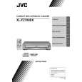
Removing the sub trays (See Fig.8 to 14)
Prior to performing the following procedure, remove the main tray cover and the U/D cam (U). CAUTION: Remove the sub tray assembly (4), (5), (3), (6), (2), (7) and (1) in order. When reattaching, observe the following procedure without fail. 1. Remove the sub tray (4) and (5) from the main tray upward. 2. Remove the sub tray (3) and (6) upward. 3. Similarly, remove the sub tray (2) and (7) upward. 4. At last, remove the sub tray (1) upward.
Sub tray (4) (5) (3) (6)
Fig.8
(1)
Reattaching the sub tray
Sub tray (2) (7)
1. Reattach the sub tray (1) while fitting the part f to the groove of the ACT. gear (1) marked g. CAUTION: After checking that it is in the state of Fig. 19, the sub tray 1 is attached.
Shaft h Sub tray (2)
Fig.9
Sub tray (1)
2. Reattach the sub tray (2) while inserting the shaft h into the groove i of the main tray, and at the same time, fitting the part j to the groove of the ACT. gear (1) marked k .
Part j Part f
Sub tray (7)
Move the sub tray (2) toward the tray (1). CAUTION: When Sub tray drive motor assembly is not attached, notice sub tray about the position to incorporate in order to move freely.
Marked k Groove i Marked g
3. Similarly, reattach the sub tray (7).
ACT. gear(1)
Fig.10
1-11
|