|
Dla tego produktu nie napisano jeszcze recenzji!
 ;
Wszystko w porządku.
Instrukcja czytelna i kompletna.
Dziękuję.
all right!
thank you.
;
Bardzo dobra instrukcja. Zawiera wszystko co potrzeba, polecam!
 ;
Instrukcja jest OK. Schematy czytelne, opisane niektóre procedury.
;
Instrukcja bardzo czytelna. zawiera co potrzeba. Polecam
;
...instrukcja serwisowa w pełni czytelna i kompletna. Dziękuję!
XM-2150GSX SECTION 3 ELECTRICAL ADJUSTMENT
Bias Adjustment
Note : In Bias Adjustment, adjust RV105 if any of Q108 through Q113 are replaced. Adjust RV205 if any of Q208 through Q213 are replaced. Condition : This adjustment should be performed about one minute after the remote mode is turned on at a room temperature of about 25°C. Setting :
B+, REM terminal
set Stabilized Power supply GND terminal
Procedure : 1. Turn the variable resistors RV105 (L-CH) and RV205 (R-CH) full clockwise as seen from the component side to minimize the bias current. 2. The input signal is to be no signal. 3. Apply the voltage to the B+ and REM terminals from the stabilized power supply and gradually increase it up to 14.4 V while checking for any unusual current. 4. Adjust each of RV105 (L-CH) and RV205 (R-CH) so that the power current of the stabilized power supply is increased in steps of 500 mA (total of 1 A). 5. After adjustment, check that the power current is at 1.3 to 2.0 A.
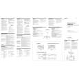
Adjustment Location : Main board (component side)
� MAIN BOARD (COMPONENT SIDE) �
RV105 BIAS ADJUSTMENT (L-CH)
RV205 BIAS ADJUSTMENT (R-CH)
8
|