|
|
|
Kategorie
|
|
Informacje
|
|
Polecamy
|
|
|
 |
|
|
Dla tego produktu nie napisano jeszcze recenzji!
 ;
Dokładna dokumentacja, pomogła w szybkiej naprawie telewizora. Dziękuję!
 ;
jedyne do czego mogę mieć zastrzeżenie to jakość zdjęć zawartych w przesłanej instrukcji serwisowej ponieważ są fatalnej jakości, praktycznie nieczytelne. tak poza tym jestem zadowolony to jest to czego szukałem.
;
Wszystko w porządku.
Instrukcja czytelna i kompletna.
Dziękuję.
all right!
thank you.
;
Bardzo dobra instrukcja. Zawiera wszystko co potrzeba, polecam!
;
Instrukcja jest OK. Schematy czytelne, opisane niektóre procedury.
XR-A100, XR-A100-K
5. ADJUSTMENT
Note: Adjustment of MYXK, NVXK and YPWXJ types are the same as those of base model except for the following.
5.1 FM/AM TUNER MODULE (AXQ7077: MYXK and NVXK types only)
7 FM Tuner Section
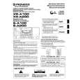
÷ Set the mode selector to FM BAND. ÷ Connect the wiring as shown in Fig. 1. FM SG (1kHz, ±75kHz dev.) Reception Step No. Adjustment Title Frequency (MHz)
1 Front End Sensitivity Stereo Distortion TUNED IND. Lighting Level
Level (dBµV) 0 to 30
Frequency Display 106 MHz
Adjustment Location
L6104 L6105 L6102 T6101 T6101
Specifications
106
Adjust so that the DC voltage between the IC6201Pin 20 and GND becomes at maximum level. Minimize the distortion with 1/8 rotation of the core. Adjust so that the indicator of TUNED IND. starts to light up.
2
98
(ON STEREO)
80 18 ± 2
98 MHz 98 MHz
3
98
VR6201
Note: Before adjusting, make sure there is no gap between L6101 and L6102 as well as between L6103 and L6104. If there is a gap between them, bring them into contact with each other first, and then make adjustments.
7 AM Tuner Section
÷ Set the mode selector to AM BAND. ÷ Connect the wiring as shown in Fig. 1. Step No. Adjustment Title AM SG (400Hz, 30% Mod.) Reception Frequency Adjustment Level Frequency Location Display (kHz) (dBµV/m) 999*1 35 to 45 999kHz*1 T6201 Specifications
1
Front End Sensitivity
Adjust so that the DC voltage between the IC6201Pin 20 and GND becomes at maximum level.
*1: For the area using 10kHz step, frequencies should be 1000 kHz.
60cm Loop antenna
AM SG
Center
Center
AM antenna terminal DC Voltmeter
MPX SG
FM SG FM75� antenna terminal
PRODUCT
Fig. 1
AM and FM Adjustment Wiring Diagram
27
|
|
|
> |
|