|
|
|
Kategorie
|
|
Informacje
|
|
Polecamy
|
|
|
 |
|
|
Dla tego produktu nie napisano jeszcze recenzji!
 ;
Dokładna dokumentacja, pomogła w szybkiej naprawie telewizora. Dziękuję!
 ;
jedyne do czego mogę mieć zastrzeżenie to jakość zdjęć zawartych w przesłanej instrukcji serwisowej ponieważ są fatalnej jakości, praktycznie nieczytelne. tak poza tym jestem zadowolony to jest to czego szukałem.
;
Wszystko w porządku.
Instrukcja czytelna i kompletna.
Dziękuję.
all right!
thank you.
;
Bardzo dobra instrukcja. Zawiera wszystko co potrzeba, polecam!
;
Instrukcja jest OK. Schematy czytelne, opisane niektóre procedury.
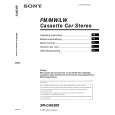
XR-CA630X
2 A
AUDIO OUT REAR
B
BUS AUDIO IN
BUS CONTROL IN
BUS AUDIO IN
Source selector Sélecteur de source
*
BUS CONTROL IN
* not supplied
non fourni
Cautions
� This unit is designed for negative ground 12 V DC operation only. � Do not get the wires under a screw, or caught in moving parts (e.g. seat railing). � Before making connections, turn the car ignition off to avoid short circuits. � Connect the yellow and red power input leads only after all other leads have been connected. � Run all ground wires to a common ground point. � Be sure to insulate any loose unconnected wires with electrical tape for safety. Notes on the power supply cord (yellow) � When connecting this unit in combination with other stereo components, the connected car circuit�s rating must be higher than the sum of each component�s fuse. � When no car circuits are rated high enough, connect the unit directly to the battery.
Connection example (2)
Notes (2-A) � Be sure to connect the ground cord before connecting the amplifier. � If you connect an optional power amplifier and do not use the built-in amplifier, the beep sound will be deactivated. Tip (2-B- ) For connecting two or more CD/MD changers, the source selector XA-C30 (optional) is necessary.
Connection diagram (3)
1 To a metal surface of the car
First connect the black ground lead, then connect the yellow and red power input leads. To the power antenna control lead or power supply lead of antenna booster amplifier Notes � It is not necessary to connect this lead if there is no power antenna or antenna booster, or with a manually-operated telescopic antenna. � When your car has a built-in FM/AM antenna in the rear/side glass, see �Notes on the control and power supply leads.�
2
Parts Iist (1)
The numbers in the list are keyed to those in the instructions.
3 To AMP REMOTE IN of an optional power
Caution
Handle the bracket 1 carefully to avoid injuring your fingers.
amplifier This connection is only for amplifiers. Connecting any other system may damage the unit.
4 To the +12 V power terminal which is
energized in the accessory position of the ignition key switch Notes � If there is no accessory position, connect to the +12 V power (battery) terminal which is energised at all times. Be sure to connect the black ground lead to it first. � When your car has a built-in FM/AM antenna in the rear/side glass, see �Notes on the control and power supply leads.� To the +12 V power terminal which is energised at all times Be sure to connect the black ground lead to it first.
1
5
4
|
|
|
> |
|