|
Dla tego produktu nie napisano jeszcze recenzji!
 ;
...instruction is ok.
...instrukcja jest ok.
Thanks/Dzięki
;
Documentation made available quickly and It is good quality. Thanks.
XV-D9000
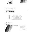
Removing the audio(rear L/R) board (See Fig.12~13)
*Prior to performing the following procedure, remove the top panel and rear cover. 1.Remove the three screws L attaching the audio(rear L/R) board. 2.Remove the four screws M attaching the audio(rear L/R) board from back of the body. 3.Disconnect the card wire from CN761 and connector from CN751 on the audio(rear L/R) board. 4.Disconnect the connector from CN697 on the audio power board. CN751 CN761 CN697 Audio-analog (rear L/R)board Fig.12 M
L
Removing the audio(front L/R) board (See Fig.14)
*Prior to performing the following procedure, remove the top panel and rear cover. 1.Remove the audio(rear L/R) board(upper step). 2.Remove the two screws N of the pillar which supports audio(rear L/R) board(upper step). 3.Remove the two screws O attaching the audio(front L/R)board(lower step). 4.Disconnect the connector from CN721 and CN722 on the audio signal(front) output terminal. 5.Disconnect the connector from CN695 and CN696 on the DVD audio power board. 6.Disconnect the connector from CN741 on the signal processing board. Signal processing board CN741
Fig.13 Audio-analog (front L/R)board
N O
CN696 CN722 CN721 CN695 Fig.14
1-10
|