|
|
|
Kategorie
|
|
Informacje
|
|
Polecamy
|
|
|
 |
|
|
Dla tego produktu nie napisano jeszcze recenzji!
CE LE N O M V EL V SU ZO D 4 D D SE BT O IM M TC T U IT M 2 P LE ER P 7 LA M EN SY N U ST 5 G EM U D V A D SY 0 3 G D M E A IN � IS P S M 8 FO � EN / LD 6 U ER � SY A X CL S 00 SU � D 00 B R IS P 9 FO TE LE LD TE ER PC EN M X T TE R + O TI M N (C ER /O LO FF A D J)
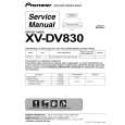
Setting Up the System Installation de l�appareil
PE D O O
1
a
Connect the subwoofer unit to the DVD/CD tuner system Branchez le caisson de basses au tuner DVD/CD
ID NO.
AN BC-HT017 9 C821 01A US WTTH ONLY E AXX7163
4
SU RE O M SE RR PE L TE TU O AT ST P U N
OPTIC DIGITAL OU AL T USE OPTIC ONLY AL DIG LINE2 WITH ITAL IN S-DV7 00SW
a
LIN E1 S-VID OUT EO VIDEO OUT VI DEO LINE1 OUT
B
A
L
AUDIO
Plug the control cable A (blue plugs) into the A jack on the rear of the DVD/CD tuner system. Plug the other end of the cable into the A jack on the rear of the powered subwoofer unit. In the same way, plug one end of the control cable B (black plugs) into the B jack on the rear of the DVD/CD tuner system, and the other end into the B jack on the powered subwoofer unit.
a
Branchez le câble pilote A (prises bleu) dans la prise A à l�arrière du tuner DVD/CD. Branchez l�autre extrémité du câble dans la prise A à l�arrière du caisson de basses asservi.
Check the supplied accessories
Confirm that the following accessories are in the box when you open it.
Vérification des accessoires fournis
Veuillez vous assurez que les accessoires suivants ont été livrés avec l�appareil lorsque vous ouvrez son emballage.
b
R
b b
c
c
De la même manière, branchez une extrémité du câble pilote B (prises noires) dans la prise B à l�arrière du tuner DVD/CD et branchez l�autre extrémité dans la prise B du caisson de basses asservi.
Remote control unit Dry cell batteries Boîtier de télécommande (size AA/R6P) x 2 Piles sèches (de type AA/R6P) x 2
V T V1/ O N O C S TA D V D ND O D B PE TR Y/O A Y FM N N C /A LO S M 0 E
Display unit (AXX7163) Unité d�affichage (AXX7163)
AM loop antenna Antenne cadre AM
FM antenna Antenne FM
c
ID NO .
AN BC-HT017 9 C821 01A
USE ON WTTH LY AXX7163
USE ONL OPTICAL LI Y WIT DIGIT NE2 H SAL IN DV70 0S B W
OPTIC DIGITAL AL OUT
A
L
LINE 1
S-VIDE OUT O
VI DEO
AUDIO
1 V 2/
R
M E EN ¡ U 7 U E
4 8 ID E V 3
M � T U N TR EEN +E
UN T+ E�
LINE1 OUT
M V O A ST SU OL T U E N V R DM P C O E
PR IN PU O A UG RATO T M RO V
D V 3 C LOD R0 S
S T
T
TE U R
T R N S
N L
TR
O
CH 1 E IO D VA N D
N U G LE A
A D
TO A N RA
CK
c
R
FRONT
L
CENT
ER
R
L
Control cable A Câble de commande A
Control cable B Câble de commande B
Display cable Câble de l�unité d�affichage
Video cord Cordon vidéo
Power cord Cordon d�alimentation
SURROU
ND
Blue plugs / Prises bleues
Black plugs / Prises noires
Gray / Gris
Yellow plugs Prises jaunes
2
a
Non-skid pads (subwoofer) x 4 Coussinets antidérapants (caisson de basses) x 4
Connect the DVD/CD tuner system to the display unit Branchement du tuner DVD/CD au display
a
Speaker cords / Cordons d�enceintes 16 ft. (5 m) x 3 (for center, front L-R speakers) 5 m x 3 (pour enceintes centrale et avant G-D)
Non-skid pads (center speaker) x 3 Coussinets antidérapants (hautparleur central) x 3
Plug the L-shaped end of the display cable into the connector on the rear of the display unit (AXX7163). Plug the other end of the display cable into USE ONLY WITH AXX7163 jack on the DVD/CD tuner system.
a
Branchez le côté en équerre du câble du display dans le connecteur à l�arrière du display (AXX7163). Branchez l�autre côté du câble du display dans la prise USE ONLY WITH AXX7163 sur le tuner DVD/CD.
b b
b
33 ft. (10 m) x 2 (for rear L-R speakers) 10 m x 2 (pour enceintes arrières G-D)
Speaker Stands x 4 Supports d�enceinte x 4
ID NO.
AN BC-H C8219 T0 1701A
US E ONLY WTTH AXX7 163
OPTICAL DI GITAL USE ONLY OUT OPTICAL LI DIGIT NE2 AL IN S-DV 700S W
WITH
B
LINE 1 S-VIDE O O UT
VI D
A
L
AUDIO
R
LINE1 OUT
Operating instructions / Warranty Mode d�emploi / Garantie
Connecting up
When connecting this system or changing connections, be sure to switch power off and disconnect the power cord from the wall socket. After completing all connections, connect the power cord to the wall socket.
Branchements
Lors du branchement de cet appareil ou du changement des branchements, vérifiez que l�appareil est débranché du secteur. Après avoir terminé tous les branchements, branchez le cordon d�alimentation au secteur.
3
Assemble the AM loop antenna Montage de l�antenne cadre AM
a b c
a
Powered subwoofer unit Enceinte active d�extrême gave
Bend the stand in the direction indicated by the arrow. Clip the loop onto the stand. If you want to fix to a wall or other surface, perform step 2 after first securing the stand with screws. It is recommended that you determine the reception strength before securing the stand with the screws.
a
Inclinez le pied dans la direction indiquée par la flèche. Clipsez la boucle dans le pied. Si vous désirez la fixer au mur ou sur un autre matériau, veuillez effectuer l�étape 2 après avoir fixé le pied à l�aide de vis. Il est conseillé de déterminer la réception avant d�assembler le support avec les vis.
b c
Display unit (AXX7163) Unité d�affichage (AXX7163)
b c
3 2
Display cable (gray) Câble de l�unité d�affichage (gris)
AM loop antenna Antenne cadre AM
4
4
R
FRONT
Connect the AM and FM antennas Branchement des antennes AM et FM
L
1
CENTE R
R
SURROU
L
ND
a
ID NO .
AN BC-HT017 9 C821 01A USE ON WTTH LY AXX7163
a
Twist off the plastic insulation on the end of each strand of the AM antenna.
a
Cassez l�isolant plastique à l�extrémité de chaque brin de l�antenne AM.
OPTIC DIGITAL AL OUT USE ONLY WIT OPTIC AL DI LINE2 GITAL H SIN DV70 0S W
LINE
1 S-VIDE OUT O
VI DEO
B
B B A
1
DVD/CD tuner system Combiné radio / DVD/CD
A
L
VIDE O OUT
AUDIO
AN
TENNA
R
LINE1 OUT
L
AM ANTENNP LOO A
b
L R
TV IN LINE1 IN
ANTEN NA
b
R
TV IN LI NE2 IN
AUDIO
FM UNBA 75� L
Connect one wire of the AM loop antenna to each AM antenna terminal. For each terminal, press down on the tab to open; insert the wire, then release to secure.
b
Connectez un câble de l�antenne cadre AM à chaque terminal d�antenne AM. Pour chaque terminal, appuyez sur l�onglet pour ouvrir, insérez le câble, et relâcher ensuite pour mettre en place le câble.
LINE1 IN
Y
4
COMPONE VIDEO NT OUT
A
Control cable A (blue plugs) Câble de commande A (prises bleues)
AUDIO
FM UNBAL 75�
AM LO ANTENOP NA
1
Control cable B (black plugs)
Y
LINE2 IN
COMPON VIDEO ENT OUT
Câble de commande B (prises noires)
c c d d
Twist off the plastic insulation on the end of each strand of the FM antenna. Connect one wire of the FM antenna to each FM antenna terminal. For each terminal, press down on the tab to open; insert the wire, then release to secure.
c
Cassez l�isolant plastique à l�extrémité de chaque brin de l�antenne FM. Connectez un câble de l�antenne cadre FM à chaque terminal d�antenne FM. Pour chaque terminal, appuyez sur l�onglet pour ouvrir, insérez le câble, et relâcher ensuite pour mettre en place le câble.
d
Non-skid pads
� Remove the paper from the non-skid pads, and stick three onto the base of center speaker. Stick the four larger pads onto the base of the subwoofer. � The subwoofer can be used laying flat, if you prefer.
Speaker Stands
� When you use the front/surround speakers on the floor, insert the speaker stand into the two central holes of the speakers.
VIDEO OUT
ANTENN
L R
AUDIO
A
FM UNB 75� AL
TV IN
AM LO ANTENOP NA
LINE1 IN
LINE2 IN
COMPON VIDEO ENT OUT
Y
Supports d�enceinte
� Si vous posez les enceintes avant/arrière sur le plancher, introduisez leur support dans les deux perçages centraux de chaque enceinte.
ANTENNA
Coussinets antidérapants
� �tez le papier recouvrant les coussinets et placez-en trois sous l�enseinte centrale. Collez les quatre coussinets les plus grands sous le caisson de basses. � Le caisson de basses peut être disposé à plat si vous préférez.
� Keep antenna cables away from other cables, the display unit and main unit. � To ensure optimum reception, make sure the FM antenna is fully extended and not coiled or hanging at the rear of the unit. � If reception with the supplied antenna is poor, see page 73 of the main Operating instructions, Connecting external antennas.
� Eloignez les câbles de l�antenne des autres câbles, du display et de l�unité principale. � Pour assurer une réception, vérifiez que l�antenne FM est complètement dépliée et pas enroulée sur elle-même ou qu�elle ne pend pas à l�arrière de l�appareil. � Si la réception à l�aide de l�antenne fournie est mauvaise, voir page 77 du Mode d�emploi, Raccordement d�antennes externes.
Remarque
FM UNBAL 75�
AM LOOP ANTENNA
|
|
|
> |
|