|
Dla tego produktu nie napisano jeszcze recenzji!
 ;
Dokładna dokumentacja, pomogła w szybkiej naprawie telewizora. Dziękuję!
 ;
jedyne do czego mogę mieć zastrzeżenie to jakość zdjęć zawartych w przesłanej instrukcji serwisowej ponieważ są fatalnej jakości, praktycznie nieczytelne. tak poza tym jestem zadowolony to jest to czego szukałem.
;
Wszystko w porządku.
Instrukcja czytelna i kompletna.
Dziękuję.
all right!
thank you.
;
Bardzo dobra instrukcja. Zawiera wszystko co potrzeba, polecam!
;
Instrukcja jest OK. Schematy czytelne, opisane niektóre procedury.
XV-M565BK/M567GD
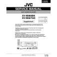
Removing the cams R1/R2 assembly and cam gear L (See Fig.23)
Slit washer 1. Remove the slit washer fixing the cams R1 and R2 assembly. 2. By removing the two pawls s fixing the cam R1, separate R2 from R1. 3. Remove the slit washer fixing the cam gear L. 4. Pull out the cam gear L from the C.G. base assembly. Cam gear L Slit washer Cam R2
L
Pawl s Pawl s Cam R1
Removing the C.G. base assembly (See Fig.23 and 24)
Remove the three screws L retaining the C.G. base assembly. [Caution] To reassemble the cylinder gear, etc.with the cam unit (cam gear and cams R1/R2 assembly), gear unit and drive unit, align the position of the pawl n on the drive unit to that of the notch on the cam gear L. Then, make sure that the gear unit is engaged by turning the cam gear L (See Fig. 24).
Cam switch board C.G. base assembly
Fig.23
Cam gear L Cam R1, R2 assembly
Notch
Pawl
n
Gear unit
Cylinder gear
Drive unit
Gear bracket
Fig.24
1-17
|