|
Dla tego produktu nie napisano jeszcze recenzji!
 ;
Schematy są ale można wysilić się i zrobić kolorowy skan i o większej rozdzielczości. Wtedy schematy płytek będą czytelniejsze. Całość super jako wartość merytoryczna. Wszystkie dane potrzebne do podłączenia różnego rodzajów urządzeń takich gramofon, CD itd.
 ;
Szybko, sprawnie i tanio. Serwis godny polecenia. Będę polecał innym
;
Ogólnie jest OK, z wyjątkiem obrazu płyty głównej, który jest miejscami mało czytelny, ale można sobie poradzić.
;
Dokładna dokumentacja, pomogła w szybkiej naprawie telewizora. Dziękuję!
;
jedyne do czego mogę mieć zastrzeżenie to jakość zdjęć zawartych w przesłanej instrukcji serwisowej ponieważ są fatalnej jakości, praktycznie nieczytelne. tak poza tym jestem zadowolony to jest to czego szukałem.
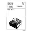
TH-V70 Removing the pre-amplifier board (See Figs. 4 to 6.)
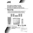
Remove the rear panel. 1. Remove the two screws F attaching the volume bracket. 2. Disconnect the pre-amplifier board from the connector CN201 on the mother board and take out the pre-amplifier board. 3. Pull out the push button. 4. Remove the two screws G and nut attaching the volume bracket.
Volume bracket Heat sink
Mother board
F
Pre-amplifier board AC bracket
H H
Power transformer
Removing the power supply & SP terminal board (See Figs. 4 and 5.)
Remove the rear panel. 1. Remove the two screws H attaching the AC bracket. 2. Disconnect the power supply & SP terminal board from the connectors CN210 and CN211 on the mother board.
Pre-amplifier board Volume bracket
Fig.4
CN201
CN101
Mother board CN211
CN111
3. Disconnect the wire from connector CN107 on the power supply & SP terminal board. 4. Disconnect the power cord from connector CN108 on the power supply & SP terminal board.
Power supply & SP terminal board
CN210
CN110
CN108
CN107 Power cord
Fig.5
Volume bracket Nut
Pre-amplifier board
G
Push button CN101
G
Fig.6 1-17
|